Digi-Stop™ Installation & Operation
WARRANTY Accurate Technology, Inc. warrants the ProScale Systems against defective parts and workmanship for 1 year commencing from the date of original purchase. Upon notification of a defect, Accurate Technology, Inc., shall have the option to repair or replace any defective part. Such services shall be the customer's sole and exclusive remedy. Expenses incidental to repair, maintenance, or replacement under warranty, including those for labor and material, shall be borne by Accurate Technology, Inc.
TABLE OF CONTENTS SECTION 1 GENERAL INFORMATION .................................................................. 4 Introduction....................................................................................................... 4 About This Manual ........................................................................................... 4 Specifications ................................................................................................... 5 DigiStop Parts ...............................
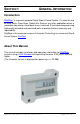
SECTION 1 GENERAL INFORMATION Introduction DigiStop is a general purpose Digital Stop & Fence System. It is ideal for use on Miter saws, Chop Saws, Radial Arm Saws or any other application where a moveable stop along a fixed back fence is desired. It has been designed using high quality extruded and machined parts to provide the best accuracy and repeatability.
Specifications 1 Measuring Range : DigiStop4 DigiStop-8 DigiStop-10 2 up to 50 inches up to 94 inches up to 116 inches (1.3 meters) (2.4 meters) (2.9 meters) Accuracy : +/- 0.015 inches (0.4 mm) Resolution .1inch .01inch .001inch 1/16inch Repeatability: .001in or .01mm Display Range: ± 999.999 in; Operating Temp: 32 to 120F Max. Slew Rate: 40 inches/sec. (1m/sec) Power: 1 CR123 3V Lithium battery (or equivalent) .1mm .01mm .01mm 1/32inch or or or 1/64 inch ± 399 63/64 in, ± 9999.
DigiStop Parts Each Digi-Stop is shipped in one or two packages (depending on the model). The first contains the Fence extrusion with the Scale attached. The second package (if necessary) contains the Digital Stop and installation hardware. Pictured below are parts that will be referred to throughout this manual.
SECTION 2 INSTALLATION Mounting the Fence Assembly 1. Align the Fence Assembly adjacent to the saw (Scale is to the rear of the fence). 2. Mark a line on the table top, along the front edge of the Fence. 3. Remove the Fence assembly and mark a second line 7/8 inch (22mm) behind the first line (this is the centerline of the Fence). 4. Drill mounting holes (at least 2) into the tabletop along the centerline of the Fence. 5. Insert the supplied 10mm bolts through the table from the top.
Calibration 1. Check to be sure installation of all parts is complete, all fasteners are secure and the Encoder is plugged into the Readout. 2. Cut a small part (approximately 8 inches) using the stop. DO NOT MOVE THE STOP UNTIL THIS PROCEDURE IS COMPLETED. 3. Measure the length of the part with the most precise measuring tool you have available (preferably digital calipers). 4.
Changing the Batteries A low battery indicator will appear in the lower left corner of the LCD. When battery voltage drops below approximately 2.6V the readout will turn itself off until the batteries are replaced. To replace the battery remove the screws in the upper right and lower left corners. Pull the cover off. Remove the old batteries. Reinstall 2 new AA Alkaline batteries, noting the proper orientation. Replace the cover and tighten the screws.
SECTION 3 OPERATION Readout Keys Key Timing The keys pictured above, are found on all Digi-Stop readouts, and some of them have multiple functions. Timing, which is how long a key is depressed, and the combination of the keys pressed is important. This manual uses the term ‘”momentarily” to describe a key press of shorter than 1 second. Whereas the term “press and hold” is used to describe a key press of longer than 1.5 seconds.
illuminated bar indicates an additional 1/64 of an inch of measurement.) For better resolution, switch to 1/32 or 1/64 mode. For the best resolution and accuracy switch to a decimal mode – inches or millimeters.. When the measurement is greater than 99 63/64 inches, a +100 and/or +200 will illuminate in the upper right portion of the display to indicate this amount must be added to the displayed reading. ie: If the measurement is 154 5/8 inches, 54 5/8 and +100 will be illuminated on the display.
Lock Mode To activate the Lock function Press and hold the ON/OFF key and then momentarily press the UNITS key. The word LOCK will appear in the upper left corner of the readout. When LOCK is displayed, the +, DATUM and – keys become inactive to prevent accidental changes of the (calibrated) current displayed position. To de-activate the Lock function, press and hold the ON/OFF key and then momentarily press the UNITS key. NOTE: The Lock function can also be enabled/disabled through programming.
if one was entered, and may be changed by using the + or - keys to provide a different offset. Moving the stop in either direction will display the distance moved from the initial INC starting point (plus any offset). To complete another incremental measurement from the new position, momentarily press the UNITS key. The readout will again change to 0 (or the previously programmed offset). To return to the ABS mode, press and hold the UNITS key for approximately 3 seconds.
Readout Programming Several functions of the Digi-Stop readout is user programmable. The following describes what features and functions are available and how to change the factory defaults to customize your Digi-Stop system.. To enter Programming Mode: 1. Press and hold the UNITS key then momentarily press the DATUM key. 2. The LCD will briefly display: PG on (Programming On), then Pr 1, (indicating Programming Parameter #1) 3. Release the UNITS key 4. The value stored in Pr1 is displayed.
Programming Parameters The Digi-Stop readout programming parameters are listed below. Values in [ ] are the available range of values that can be entered for that parameter. Factory defaults are shown in Bold Red. Pr 1 – Datum Key [0 to + 999.999in] or [0 to +9999.99mm] The programmed value that will be recalled whenever the DATUM key is pressed during normal operation. Default = 0.00 Pr 2 – Reverse Readings [0 or 1] This parameter controls the direction of travel (positive vs.
Thank you for choosing an AMERICAN MADE PRODUCT Accurate Technology, Inc. 270 Rutledge Rd. Unit E Fletcher, NC 28732 USA 828.654.7920 Please register your product at: http://www.proscale.com/registration.htm This manual is available online at: www.proscale.com Manual P/N 800-1070-001 Rev112012.