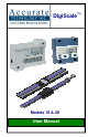
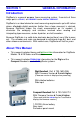
DigiScale Models 18 & 28 User Manual ™
DigiScale Manual Part # 800-1404-001 Page 2 of 36
WARRANTY Accurate Technology, Inc. warrants the DigiScale Models 18 & 28 against defective parts and workmanship for 1 year commencing from the date of original purchase. Upon notification of a defect, Accurate Technology, Inc., shall have the option to repair or replace any defective part. Such services shall be the customer's sole and exclusive remedy.
Table of Contents SECTION 1 GENERAL INFORMATION................................................. 6 INTRODUCTION........................................................................................... 6 ABOUT THIS MANUAL .................................................................................. 6 SPECIFICATIONS......................................................................................... 6 SPECIFICATIONS..................................................................................
SECTION 4 COMPACT READOUT .............................................24 MOUNTING ...............................................................................................24 Surface Mount Configuration................................................................24 Panel Mount Configuration...................................................................25 THE LCD .................................................................................................26 CHANGING THE BATTERY ...........
SECTION 1 GENERAL INFORMATION Introduction DigiScale is a general purpose linear measuring system It consists of three major parts: a SCALE, an ENCODER and a DIGITAL READOUT. DigiScale is an ideal choice for most measuring requirements up to 60 inches where affordable digital precision (better than a tape measure) is desired.
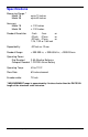
Specifications Measuring Range: * Model 18 Model 28 up to 10 inches up to 60 inches Accuracy: Model 18 Model 28 ± .010 inches ± .012 Inches Readout Resolution .1inch .1mm or .01inch .01mm or .001inch .01mm or 1/16, 1/32 or 1/64 inch Repeatability: .001inch or .01mm Readout Range: + 999.999 in; + 399 63/64 in; + 9999.
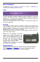
About DigiScale All DigiScale systems consist of a SCALE (or track), an readhead) and a DIGITAL READOUT (DRO). ENCODER, (or Scale DigiScale Models 18 & 28 The scale consists of a series of conductive patterns bonded to an aluminum extrusion. The Model 18 Scale is .765 inches wide and comes in measuring lengths up to 10 inches long. The Model 28 Scale is 2.02 inches wide and comes in measuring lengths up to 60 inches.
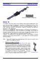
SECTION 2 INSTALLATION End view of Model 18 DigiScale Model 18 The Model 18 can be used in many different measurement applications, and with numerous types of equipment. Therefore all installations will be a little different and it is the responsibility of the user to choose the bolts, screws, or other mounting hardware that provides a quality installation and optimum operation in their application. Determine an appropriate mounting location and position for DigiScale in your measuring application.
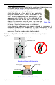
2. Stationary Scale installation If your application is better suited for the scale to be held stationary and the encoder moved along it during a measurement, you should use the Guide Clip to capture the encoder and move it along the scale (see illustration). Attach the scale to a fixed point in your application using the included screw. Place the encoder on the scale.
End view of Model 28 DigiScale Model 28 The Model 28 can be used in many different measurement applications, and with numerous types of equipment. Therefore all installations will be a little different and it is the responsibility of the user to choose the bolts, screws, or other mounting hardware that provides a quality installation and optimum operation in their application. Determine an appropriate mounting location and position for DigiScale in your measuring application.
moved (the guide clip will compensate for slight misalignment in the direction perpendicular to movement). Adjust the scale alignment if necessary. Plug the encoder cable into the readout. Refer to the Digital Readout OPERATION manual that accompanied your DigiScale. M o v in g P a r t G u i d e C l ip E n co de r M o d e l 2 8 S ca le G u id e C li p E ncod er ( .8 3 " ) M od el 28 S c a le ( 1 .
Frequently Asked Questions Can I mount the Scale/Encoder without the connector link/guide clip? Yes. However, the connector link and guide clip serve to provide an accurate method of transferring the movement of the encoder or scale, while also absorbing any stresses that may occur. If they are not used, your system could be damaged and the warranty could be voided. What does no Enc mean? If the encoder is off the scale, or unplugged from the readout, a no Enc will appear on the readout.
SECTION 3 DIGI READOUT This Section includes information for: Digital Readout, LCD, DIGI Part Number: With Firmware Version d 2.xxx & higher (Firmware version is displayed on power-up) 700-1600-D55 Mounting The Readout may be mounted: • Using Velcro or Double sided tape • Drilling out the 3 holes from the inside of the case • Using any of the six holes on the back of the case which may tapped for M2 or 4-40 screws.
The LCD The above figure illustrates all the segments available on the Dig Readout. (Not all segments are used) CAUTION Pressing and holding the ON/OFF and UNITS key for 10 seconds with power off will perform a full segment LCD test, display the current firmware version, and RESET ALL PROGRAMMING PARAMETERS TO FACTORY DEFAULTS.
Changing the Batteries A low battery indicator will appear in the lower left corner of the LCD. When battery voltage drops below approximately 2.6V the readout will turn itself off until the batteries are replaced. To replace the battery remove the screws in the upper right and lower left corners. Pull the cover off. Remove the old batteries. Reinstall 2 new AA Alkaline batteries, noting the proper orientation. Replace the cover and tighten the screws.
Circuit Board Jumpers The Digi readout has several user configurable jumpers consisting of three pins and a ‘shorting block or jumper’. The center of these three pins is ‘Common’. One end pin is labeled A and the other end pin is labeled B.
Operation Readout Keys TIMING The keys pictured above, are found on all Digi readouts, and some of them have multiple functions. Timing, which is how long a key is depressed, and the combination of the keys pressed is important. This manual uses the term ‘”momentarily” to describe a key press of shorter than 1 second. Whereas the term “press and hold” is used to describe a key press of longer than 1.5 seconds.
better resolution, switch to 1/32 or 1/64 mode. For the best resolution and accuracy switch to a decimal mode – inches or millimeters. When the measurement is greater than 99 63/64 inches, a +100 and/or +200 will illuminate in the upper right portion of the display to indicate this amount must be added to the displayed reading. ie: If the measurement is 154 5/8 inches, 54 5/8 and +100 will be illuminated on the display.
INCREMENTAL MEASUREMENTS The readout has two measurement modes, or indexes. One is referred to as ABS or Absolute, and the other as INC, or Incremental. The absolute measurement mode allows the operator to read the current position of the encoder referenced from a fixed or known position-usually zero. The incremental mode allows the operator to make relative distance measurements from one arbitrary point to another. The absolute position of the DigiScale is not lost when using the incremental mode.
KEY LOCK To activate the Key Lock function press and hold the ON/OFF key and then momentarily press the UNITS key. The word LOCK will appear in the upper left corner of the readout. When LOCK is displayed, the +, DATUM and – keys become inactive to prevent accidental changes of the (calibrated) current displayed position. To de-activate the Lock function, press and hold the ON/OFF key and then momentarily press the UNITS key. NOTE: The Lock function can also be enabled/disabled through programming.
Programming Several functions of the Digi readout are user programmable. The following describes what features and functions are available and how to change the factory defaults to customize your DigiScale system. To enter Programming Mode: 1. Press and hold the UNITS key then momentarily press the DATUM key. 2. The LCD will briefly display: PG on (Programming On), then Pr 1, (indicating Programming Parameter #1) 3. Release the UNITS key 4. The value stored in Pr1 is displayed.
Programming Parameters The Digi readout programming parameters are listed below. Values in [ ] are the available range of values that can be entered for that parameter. Factory defaults are shown in Bold Red. Pr 1 – Datum Key Value [0 to + 999.999in] or [0 to +9999.99mm] The programmed value that will be recalled whenever the DATUM key is pressed during normal operation. Default = 0.00 Pr 2 – Reading Direction [0 or 1] This parameter controls the direction of travel (positive vs.
SECTION 4 COMPACT READOUT This Section includes information for: Digital Readout, LCD, Compact Part Number: 700-1600-710 With Firmware Version b 1.xxx & higher (Press the DATUM key for 7 seconds to display Readout Firmware version) Mounting Surface Mount Configuration The Compact readout may be mounted: • Using Velcro or Double sided tape • Punch out any of the four holes from the inside of the back case. • Using any of the four holes on the back of the case.
Panel Mount Configuration A cutout should be made in the panel of at least 2.2 x 1.7 inches, (56 x 43mm) but no larger than 2.6 x 2.0 inches (66 x 50 mm). Install the readout by screwing the four screws in the each corner of the front case directly into the panel. The rear half of the readout case is not necessary when it is used in a panel mounted configuration with a panel of sufficient thickness to hold the 4 mounting screws.
The LCD The above figure illustrates all the segments on the LCD display. (Not all segments are used on Compact Readouts) Changing the Battery A low battery indicator will appear in the lower left corner of the screen on the readout when a new battery is needed. To replace the battery, remove the 4 screws in the corners of the readout case. Separate the two cases, remove the battery clip and the old battery. Install a new CR123 3V, or equivalent, Lithium battery, noting the proper orientation.
Circuit Board Jumpers The Compact readout has several user configurable jumpers consisting of three pins and a ‘shorting block’ or ‘jumper’. The center of these three pins is common. One end pin is labeled A and the other end pin is labeled B. JP1 FACTORY USE ONLY JP2 Programming Lock-out Front panel programming of the Compact readout can be enabled or disabled with a circuit board jumper. Programming is enabled when the shorting jumper is installed on position A. To disable programming, install it on B.
Operation Readout Keys TIMING The keys on your readout, illustrated below, have multiple functions. Timing, (how long a key is depressed) is important. This manual uses the terms “momentarily” to describe a key press of less than 0.8 seconds and “press and hold” to describe a key press of 2 seconds or longer. See Table Below. How long a key is pressed? When is key function is executed? Momentarily Less than 0.
IN/MM KEY Momentarily press The compact readout can display measurement/position information in inches, fractions or millimeters. To change the display mode, momentarily press the IN/MM key. Each key press causes the readout to cycle to the next mode, or unit of measurement: decimal inches, fractions 16ths, fractions 32nds, fractions 64ths and millimeters.
DATUM KEY Momentarily press The DATUM key is used to change the currently displayed value. Momentarily pressing the DATUM key forces the readout to a user programmed value. This can be zero or any other displayable value. See Section 4: Programming, Programming Parameter Pr1 The DATUM key can also be locked out to prevent accidental entries. See Section 4: Circuit Board Jumpers, JP 2 Press & Hold Additional functions of the DATUM key: Press and hold DATUM for 7 seconds to display the firmware version.
Readout Functions REVERSE READINGS Reverse readings means changing the direction of readings produced by moving the encoder. If the readout decrements (reduces or goes negative) when it should be incrementing (increasing or going positive), the readout will need to be re-programmed for your application.
NOTES: 1. Offsets are stored when leaving the Incremental mode. Any offsets will be recalled the next time you switch from Absolute to Incremental mode. 2. While in Incremental mode, the Units of Measurement cannot be changed. If the display is reading mm when you enter the INC mode you cannot change to inches without first returning to the ABS mode. KEY LOCK The user can lock-out the operation of the +, DATUM and – key functions to prevent accidental changes of the currently displayed value.
Programming Several functions of this readout are user programmable. The following describes what features and functions are available and how to change the factory defaults to customize the system to suit your application needs. To enter programming mode: Press and hold the DATUM key. After approximately 7 seconds the readout firmware version (b 1.xxx) will be displayed for 2-3 seconds and then the readout will enter programming mode. PR 1 is displayed, immediately followed by the programmed value for Pr1.
Programming Parameters Compact Readout Programming Parameters are listed below. Values in [ ] are the available range of values that may be programmed for that parameter. Factory defaults are shown in Bold Red. Pr 1 – Datum Key Value [0 to + 999.999in] or [0 to +9999.99mm] This value will be recalled and displayed when the DATUM key is pressed during normal operation (not during programming).
Accurate Technology DigiScale Models 18 & 28 User Manual Page 35 of 36
Thank you for choosing an AMERICAN MADE PRODUCT Accurate Technology, Inc. 270 Rutledge Rd. Unit E Fletcher, NC 28732 USA 828.654.7920 Please register your product at: http://www.digi-kit.com/registration.htm This manual is available online at: www.digi-kit.com Part # 800-1404-001 Copyright © 2008, Accurate Technology, Inc. All rights reserved.