
User`s manual
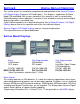

ProScale M150, M250 and all products with General Purpose LCD Digital Displays 26 of 44
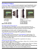
+, 0, and – Keys
The + (plus), 0 (zero) and – (minus) keys are used to change the currently displayed
position to a different value. The 0 key forces the unit to display 0. Momentarily
depressing the + key increments the current position by one unit of measurement.
Momentarily depressing the – key decrements the current position by one unit. Pressing
and holding the + or – keys will cause the displayed position to change continuously.
Holding down the key will cause the amount of change to speed up. This allows for quick
adjustments over a range of large values. These keys can be “locked out” to prevent
accidental offset or zero entries. (See Programming Parameter Pr3)
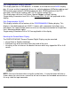
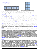
Digital
Display Functions
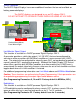
Lock Mode
The user can “lock-out” the position offset adjustment functions (+, -, 0 keys) to prevent
accidental changes of the current displayed position. To activate the lock mode, press
and hold the ON/OFF key and then momentarily press the MODE key. The word LOCK
on the LCD display will turn on or off with each lock/unlock operation. When the LOCK
symbol is displayed, the +, - and 0 keys will not change the displayed position. On
Displays with an auxiliary keypad: ABS and INC modes have independent lock
operations. (See Programming Parameter Pr3. Factory default is Enabled.)
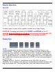
Segment Offset Adjustment
For scales that are longer than 430mm (17 inches), multiple scale pattern segments are
installed end-to-end on the aluminum extrusion. This provides a quasi-absolute
measurement capability in which the readhead can calculate its position on any individual
scale segment but cannot determine which particular segment it is on. To solve this
problem, the Digital Display tracks which scale segment the readhead is on by detecting
the “splice” between one segment and adjacent segments.
In certain situations, the crossing from one segment to another may not be detected by
the display. This may occur if the readhead is disconnected from the digital display and
then moved along the scale to another segment. It may also occur if the readhead is
moved too quickly between two segments. (Maximum slew rate is 400mm/sec, 15in/sec)
If the segment tracking count is incorrect because of one of the above situations, the user
can re-adjust the display to correct the error. This adjustment is referred to as the
Segment Offset Adjustment.
To add one segment value (430.08mm) to the displayed value, hold the MODE key and
then momentarily press the + key. The displayed position will increase by 430.08mm
(16.933 inches). To subtract one encoder segment from the displayed value, press and
hold the MODE key and then momentarily press the - key. The displayed position will
decrease by 430.08mm.
(See Programming Parameter Pr1 and SCALES in Section 1 of this manual for
additional information. Factory Default is set to Enable this function.)