
User Manual


Chapter 1 – Introduction
9
Familiarizing yourself with the controller
Overview
The RAID box has two drive carriers, accessed from the front.
The sides of the box each feature a guide rail channel and mounting screw holes to enable
the box to be secured inside a computer case.
The connectors and jumpers are located on the rear panel.
Top /Down Drive carrier
Rebuilding activity/Error message
indicator
Disk status/ Rebuild indicators
Guide rail channel
Holes for mounting screws
Rear / Connectors & jumpers
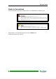
Front view
Two Drive Carriers
Disk Activity Indicators
Drive Carrier Lock
Each drive carrier can hold a one-inch high 3.5-inch form factor hard disk drive. This makes it
easy to hot swap a drive in the event of a failure, without affecting the status of the remaining
drives.
Drive Carrier Lock – Unlocked
orientation
Drive Carrier Lock – Locked
orientation
Green Disk Activity Indicator
Amber Disk Activity Indicator
Red Disk Activity Indicator