A16R/A16U-IS Quick Start Guide ExaRAID SYSTEM USER'S GUIDE
A16R/A16U-IS Quick Start Guide 42-33000-5031 ExaRAID SYSTEM Version:1.
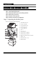
Accusys A16R/A16U-IS Accusys RAID System Task List Step 1. Unpacking the RAID system Step 2. Mounting the RAID System and Installing Hard Disk Step 3. RAID System Connections Step 4. Setting the LAN Connection Step 5. Disk Array and iSCSI Port Configuration Step 1. Unpacking the RAID system The box contains the following items: 1. Hard disk trays x 16 2. Screw x 3 packs 1 3. Front panel key x 2 4. RS-232 cable x 2 8 2 3 9 4 10 11 12 13 Quick Start Power P/S Fail Access Enter ESC Guide 5.
Accusys A16R/A16U-IS Step 2. Mounting the RAID System and Installing Hard Disk Mounting the RAID system The RAID system/Rail Extenders can be installed in a standard 19-inch rack. Follow the procedures below: 1. Attack eight rack nuts into the rack, making sure that they correspond with the mounting points on the rails. 2. Adjust the length of the rails as needed. 3. Secure the rails using two nuts and bolts on both the front and back posts of the rack then tighten the locking screws. 4.
Accusys A16R/A16U-IS Installing the Rail Extenders If the front door was stocked by abstacle chassis at botton side, please follow the procedures below to install the rail extenders. Follow the procedures below to install the rail extenders: 1. Install the rail extenders and attach the screws to secure them. 2. Slide the RAID system into the rack and secure it into place using the fixing screws.
Accusys A16R/A16U-IS Installing the Hard Disks The RAID system supports SAS or SATA interface hard drives. Caution It is recommended to mount the RAID system to the rack cabinet first before installing the hard drives and the drive trays. If the hard drives are installed first, the RAID system may be too heavy to lift or handle. And the possible impact during installation may damage the drives. Follow the procedures below to install hard drives: SAS hard disks 1.
Accusys A16R/A16U-IS 3. Pull open the front panel door. 4. Insert the hard disk trays into the empty slots. 5. Push down the tray handle to secure the hard disk tray into place. 6. Repeat steps 4 to 5 until all the required disks have been installed. 7. Close the front panel door, then lock it.
Accusys A16R/A16U-IS SATA hard disks SATA hard drive installation requires an AA-MUX adapter to be installed on the hard disk tray first before installing the SATA hard disk. Note AA-MUX is an optional accessory and is sold separately. Contact your supplier to purchase one. Follow the procedures below to install SATA hard disks: 1. Place the AA-MUX adapter on the hard disk tray and attach the four screws as shown. 2.
Accusys A16R/A16U-IS 3. Slide the hard disk towards the AA-MUX adapter and connect the power and data connectors. 4. Attach the screws to secure the hard disk. Note Please run DST (disk self test) function to verify the status of each disk before starting to configure the disk array, refer to the Software User Manual for detailed procedures.
Accusys A16R/A16U-IS Step 3. RAID System Connections Connecting RAID System to the Host There were 4 iSCSI channel interfaces on each controller. Each channel interface can be connected using standard Gat5/6 Ethernet cables. You can configure your RAID system for Direct Storage (DAS) by directly connecting to a host server or through an inexpensive gigabit Ethernet switch to build a Storage Area Network (IP-SAN). To connect the Ethernet cable: 1. Insert the cable to the CH port. 2.
Accusys A16R/A16U-IS 2. Connect the other end to the CH1 port of SAS JBOD enclosure. 3. After connecting the SAS connector, turn the power of the JBOD first, and then turn the power of the RAID system. 4. Power/Fan/Temp/HDD LED on JBOD lights up green and IO1&2 LED flashes when the connections are set up properly. Connecting the Power Once all of the components have been installed into the RAID system, and the management interfaces have been connected, the RAID system can now be powered on. Power on: 1.
Accusys A16R/A16U-IS By GUI 1. Open a browser and enter the RAID system’s IP address in the address field. (The default IP address is 192.168.0.1) 2. Log in from GUI to open the Config Mode. The default username and password are “admin” and “0000”. 3. Click System Management > Restart/Halt to open the Restart/Halt page. 4. Select Both Controllers from the Controller ID drop down menu and select Halt from the Action drop down menu and click Apply. 5. Click Confirm to confirm and shut down the system. 6.
Accusys A16R/A16U-IS Choosing DHCP or a Static IP Address When you setup your RAID system, you have the option of: • Enabling DHCP and letting your DHCP server assign the IP address to the RAID system’s virtual management port. • Specifying a static IP address for the RAID system’s virtual management port. Press Enter and ESC buttons twice simultaniously on LCD to know the current IP, linked to the RAID system’s GUI.
Accusys A16R/A16U-IS Step 5. Disk Array and iSCSI Port Configuration I. Build a DAS with Clustering Environment This page will show steps to build an DAS with clustering server environment. Array volume will be presented as a block-based storage device (like SCSI disk) to two clustering server nodes by through traditional Ethernet. Follow the steps below to configure RAID. Clustering Server 0 Clustering Server 1 hear-beat Ist0: 192.168.2.10 Ist1: 192.168.2.
Accusys A16R/A16U-IS II. Build an IP-SAN with Active-Active Redundant environment This page will show steps to build an active-active redundancy environment without single point of failure in between controllers, paths and switches. Follow the steps below to configure RAID system. Server 1 Server 0 A iSCSI target portal B A Ist0: 192.168.2.10 Ist1: 192.168.2.12 B Ist0: 192.168.2.10 Ist1: 192.168.2.12 GbE switch GbE switch Ist0:192.168.2.10 (Aggregation) Ist1:192.168.2.
Accusys A16R/A16U-IS A. Pre-Setting Open GUI Management by Web Browser 1. Open a browser and enter the IP address in the address field. The supported browsers are IE 6.x, FireFox 1.x, Safari 1.x and above. 2. The following web page appears when the connection is made. To login, enter the username and password. The default username and password are “admin” and “0000”. You can then access the Config Mode.
Accusys A16R/A16U-IS Run Disk Self Test to verify Hard Disk 1. DST (Disk Self Test) is needed to enable disk SMART function, click Hardware Configurations -> Hard Disks from config menu, select ON to enable disk SMART Warning function. 2. Click Maintenance Utilities -> Disk Self Test from config menu. The following screen appears.
Accusys A16R/A16U-IS 3. Click disks from disk table and press DST button, the following screen appears. 4. Click Perform extended disk self test and Confirm button to start verify the status of disk, it will takes a period of time, depend on different disk capacity. 5. Exchange the disk failed at DST test. Enable Battery Backup Module If BBM (Battery Backup Module) is installed, follow steps below to enable BBM function. 1. Click Maintenance Utilities -> Disk Self Test from config menu.
Accusys A16R/A16U-IS B. Create Disk Groups 1. Open a browser and enter the IP address in the address field. The supported browsers are IE 6.x, FireFox 1.x, Safari 1.x and above. 2. The following web page appears when the connection is made. The default username and password are “admin” and “0000”. 3. To make sure the hard disks are unused, click RAID Management from the Config Mode menu to check the status.
Accusys A16R/A16U-IS 4. Click Disk Groups from the menu. The following screen appears. 5. Click Create to open Create Disk Group screen. 6. Select a DG ID from the drop-down menu. 7. Highlight the disks to be grouped in Members and Spares and click to move them to the Member Disks. 8. Click Apply to create the disk group. 9. Repeat steps 4 to 8 to create other disk groups.
Accusys A16R/A16U-IS C. Create Logical Disks 1. Click Logical Disks from the Config Mode menu. The following screen appears. 2. Click Create to open Create Logical Disk screen. 3. Select a DG ID from the drop-down menu. This is the disk group to be assigned for logical disk setting. 4. Select an LD ID from the drop-down menu.
Accusys A16R/A16U-IS 5. Use the system default name as dgxldy. ‘x’ is the DG identifier and ‘y’ is the LD identifier. OR Uncheck the ‘Use system default name’ box and enter the name in the Name field. 6. Select a RAID level for the logical disk. Different logical disks in a disk group can have different RAID levels. However, when NRAID is selected, there must be no non-NRAID logical disks in the same disk group. 7. Enter an appropriate capacity for the logical disk.
Accusys A16R/A16U-IS D1. Set iSCSI Port 1. Click Hardware Configurations > iSCSI Ports from the Config Mode menu. The following screen appears. This page displays iSCSI ports status and allows users to configure all iSCSI functions. 2. Choose an iSCSI port and click Modify to change port configuration. 3. Enter the IP Address, Network Mask, and Gateway for the port. 4. Click Enable Jumbo Frame to enable Jumbo frame function. Note Jumbo Frame requires all network switches and host devices to be enabled.
Accusys A16R/A16U-IS D2. Set iSCSI Aggregation Port 1. Click Aggregate to create aggregation. 2. Select the Assignment Method from the drop-down menu. 3. Enter the IP Address, Network Mask, and Gateway for aggregation port. 4. Click Enable Jumbo Frame to enable Jumbo frame function. Note Jumbo Frame requires all network switches and host devices to be enabled. 5. Highlight the ports from the Unbind ISP Port and click to the Bind ISP Port.
Accusys A16R/A16U-IS 6. Click Apply. The following confirmation message is displayed. 7. Click Confirm to complete aggregate. Note To remove an aggregate, click the iSCSI port you want to remove then click the RM-Aggr button.
Accusys A16R/A16U-IS E. Set iSCSI Target 1. From the iSCSI Ports page, click Target to open the iSCSI Target Node page. 2. Click Create. 3. Select the IST ID from the drop-down menu. 4. Enter the target name and alias (optional). 5. Select either CHAP or None from the Authentication method dropdown menu. 6. Highlight the ports from the Unbind ISP Port and click to the Bind ISP Port. to move them 7. Click Apply to create the iSCSI target node. Note • Only a maximum of 8 target nodes can be created.
Accusys A16R/A16U-IS F. LUN Mapping 1. Click RAID Management > Storage Provisioning from the Config Mode menu. The following screen appears. 2. Click Add to open Add LUN to Storage Port screen. 3. Select an HTP ID from the drop-down menu. 4. Select a LUN ID from the drop-down menu. 5. Select a virtual disk from the drop-down menu for LUN mapping. 6. Click Apply to set LUN mapping. 7. Repeat steps 2 to 7 until you have assigned all the virtual disks.
Accusys A16R/A16U-IS G. Set iSCSI Initiator on Windows iSCSI is an Internet Protocol-based storage networking standard for linking data storage facilities. By carrying SCSI commands over IP networks, iSCSI is used to facilitate data transfers over intranets and to manage storage over long distances. iSCSI can be used to transmit data over local area networks (LANs), wide area networks (WANs), or the Internet and can enable location-independent data storage and retrieval.
Accusys A16R/A16U-IS 2. Click the Discovery tab. 3. Click the Add Portal button to open the Add Target Portal window. 4. Enter the target IP address, click OK.
Accusys A16R/A16U-IS 5. Click the Targets tab. The available iSCSI targets are listed on screen. The default the target status is Inactive. 6. Select an iSCSI target, then click Log on. 7. On the Log On to Target window, click Automatically restore this connection when the computer starts, then click OK. The target status becomes Connected.
Accusys A16R/A16U-IS 8. If a acitve-active environment is configured, click Advanced to set the Target Portal, ist0 select IP192.168.2.10(controllerA), ist1 select isb IP192.168.2.12(controllerB). 9. Make sure the two installed disk devices are in the Disk Management as shown in the illustration. After that, you may format the new disk devices and start using them.
Accusys A16R/A16U-IS H. Set PathGuard on Windows 2003 Server PathGuard is the bundled multi-path IO solution for Windows 2003, 2003 R2 32bit / 64bit, platforms, and it is based on Microsoft Multipath I/O (MPIO) framework. PathGuard consists of MPIO drivers and a web-based path manager GUI that allows you to manage MPIO configurations for multiple host computers. The MPIO drivers include standard drivers from Microsoft and DSM (Device Specific Module) provided by the RAID system supplier.
Accusys A16R/A16U-IS To Install PathGuard and MPIO Driver: 1. To install the PathGuard and MPIO Driver, double click the installation file on a host computer (choose the 32-bit or 64-bit installation file according to your host system). 2. Follow the on-screen instructions to start the installation. PathGuard and the MPIO Driver will be installed automatically. 3. Reboot the host computer, and you have completed the installation.
Accusys A16R/A16U-IS 1. Go to Computer Management > Device Manager > Disk Drivers and SCSI and RAID controllers to check for the Multi-Path Disk Device and Multi-Path Support. The following illustration shows a successful installation with Multi-Path Disk Device and Multi-Path Support found in the Device Manager. 2. Make sure the two installed disk devices are in the Disk Management as shown in the illustration. After that, you may format the new disk devices and start using them.
Accusys A16R/A16U-IS Troubleshooting General Guidelines When you encounter issues, the most essential troubleshooting is to check the event log of your RAID system. In addition, you may need to check the system log of the operating system at your host computers. Because there are a wide variety of hardware and software combinations, use the following checklist for problem determination: • Check all cables to make sure they are connected properly.
Accusys A16R/A16U-IS • Disk bad block over threshold warning. • Disk group with degraded logical disk and no disk for rebuilding. • Disk group with faulty logical disks. • UPS failure or error. • Controller failure or removed. • Dual controllers fail to boot up because of configuration conflict. • Controller failback cannot proceed. Solutions See the table below for the solutions for the most common problems.
Accusys A16R/A16U-IS Multiple hard disks Could be system-level Use array recovery utility to the RAID are taken offline at a problem. For example, if the configurations. See the User’s mantime. hard disks in a JBOD system ual for more details. are offline unexpected, poor cabling in SAS or SAS expansion chain would also lead to unexpected hard disk offline. In addition, poor heat ventilation, unstable power supply, or hardware quality issues could also lead to offline of multiple hard disks.
Accusys A16R/A16U-IS The replacement controller stops bootup with LCD messages. If the conflict configuration can be resolved by overwriting the configuration of the replacement controller, the following LCD messages will be displayed and waiting for your confirmation by LCD ENT button: (H) CHK BC VERS: the two controllers have different boot code version. (I) CHK FW VERS: the two controllers have different firmware code version. (J) CHK BBM OPT: the two controllers have different BBM option.
Accusys A16R/A16U-IS Company Contact Accusys, Inc. • 5F., No.38, Taiyuan St., Jhubei City, Hsinchu County 30265, Taiwan(R.O.C) • Tel: +886-3-560-0288 • Fax: +886-3-560-0299 • http://www.accusys.com.tw/ • E-mail: sales@accusys.com.tw Accusys U.S.A., Inc. • 1321 W. Foothill Blvd. Azusa, CA91702 • Tel: +1-510-661-0800 • Fax: +1-510-661-9800 • http://www.accusys.com.tw • E-mail: Maggie@accusys.com.tw Accusys Korea, Inc.
Accusys A16R/A16U-IS Accusys EU B.V • Orionweg 6, 4782 SC Moerdijk, The Netherlands • Tel: +31 (0) 102995758 • Fax: +31 (0) 168358621 • http://www.accusys.com.tw • E-mail: sales@accusyseu.com, support@accusyseu.