
Instruction Manual


JBOD System Quick Start Guide
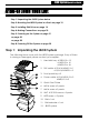
6
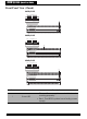
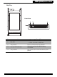
Rear View
No. Item Description
1
AC power port Connects to the power source.
2
Power supply handle Use to pull out the power supply.
3
Power supply switch Use to switch the power on or off.
4
Cooling fan 1 System cooling fan.
5
Chassis ID
Use for JBOD enclosure only, See Switch
ID on page 9.
6
UPS port
Data port for uninterruptable power
supply.
7
AC power port Connects to the power source.
8
Power supply handle Use to pull out the power supply.
9
Power supply switch Use to switch the power on or off.
10
Cooling fan 2 System cooling fan.
11
JBOD Controller A JBOD controller.
12
Expansion port (Controller A) Use for JBOD expansion.
13
Host channel 1 (Controller A)
Connects to EXP port on RAID system or
SAS HBA card of host.
14
Host channel 2 (Controller A)
Connects to EXP port on RAID system or
SAS HBA card of host.
15
JBOD Controller B JBOD controller.
16
Expansion port (Controller B) Use for JBOD expansion.
17
Host channel 1 (Controller B)
Connects to EXP port on RAID system or
SAS HBA card of host.
18
Host channel 2 (Controller B)
Connects to EXP port on RAID system or
SAS HBA card of host.
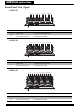
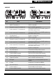
A
1
B
2
15
ON DIP
432
U
P
S
EXP CH 1 CH 2 EXP CH 1 CH 2
1
12 13 14 16 17 1811
2 3 4 75 6
15
8 9 10
A
1
B
2
15
ON DIP
432
U
P
S
EXP CH 1 CH 2
1
12 13 1411
2 3 4 75 6 8 9 10
A12R-SJ A12U-SJ