
Instruction Manual


7
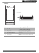
JBOD System Quick Start Guide
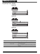
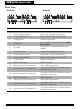
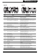
No. Item Description
1
Cooling fan 1 System cooling fan.
2
JBOD Controller A JBOD controller.
3
Expansion port (Controller A) Use for JBOD expansion.
4
Host channel 1 (Controller A)
Connects to EXP port on RAID system or
SAS HBA card of host.
5
Host channel 2 (Controller A)
Connects to EXP port on RAID system or
SAS HBA card of host.
6
Cooling fan 3 System cooling fan.
7
JBOD Controller B JBOD controller.
8
Expansion port (Controller B) Use for JBOD expansion.
9
Host channel 1 (Controller B)
Connects to EXP port on RAID system or
SAS HBA card of host.
10
Host channel 2 (Controller B)
Connects to EXP port on RAID system or
SAS HBA card of host.
11
Cooling fan 2 System cooling fan.
12
AC power port Connects to the power source.
13
Power supply 1 Removable power supply.
14
Power supply handle Use to pull out the power supply.
15
Power supply switch Use to switch the power on or off.
16
Chasis ID switch Use for JBOD enclosure only.
17
UPS port
Data port for uninterruptable power
supply.
18
IO tray Holds the IO board and BBMs.
19
AC power port Connects to the power source.
20
Power supply 2 Removable power supply.
21
Power supply handle Use to pull out the power supply.
EXP CH 1 CH 2 EXP CH 1 CH 2
Fan 1 Fan 3
Contraller A
Fan 2
Contraller B
P/S 1 P/S 2
VER 1.0
P/S
UPS
Chassis
ID
5
6
7
8
9
0
1
2
3
4
1 6
13 14 15 16 17 1812 20 2119
2 543 1098 117
EXP CH 1 CH 2
Fan 1 Fan 3
Contraller A
Fan 2
Contraller B
P/S 1 P/S 2
VER 1.0
P/S
UPS
Chassis
ID
5
6
7
8
9
0
1
2
3
4
1 6
13 14 15 16 17 1812 20 2119
2 543
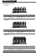
A16R-SJ A16U-SJ