
User guide

1. Do not exceed 1,500 in/min (38 m/min) velocity without consulting factory.
2. VC may be mounted in any position.
3. To prevent internal damage, do not twist (rotate) VC plunger.
0000
4. Operating temperature range: 32 to 140 F (0 to 60 C)
5. Protect unit from weld flash, petroleum based fluids and external damage.
6. Contact factory when the VC must be exposed to an oil environment.
7. Adjustment instructions:
a) To increase feed rate, rotate adjustment knob counterclockwise.
b) To decrease feed rate, rotate adjustment knob clockwise.
World leader in deceleration technology
ISO 9001:2000 Certified
ACE Controls Inc.
ACE Form 15, VC
04/01/2004
Mount on flat surfaces
using ACE mounting
block. May also be
installed in suitable
machined hole. Do
not use set screws.
Piston rod must
butt directly against
object to be controlled.
It should not contact
object at an angle
0
exceeding 1 .
Mounting Block
Mounting block can
be installed anywhere
on the body.
0
2 max
0
1 max
Optional Thread
M25 x 1.5
23435 Industrial Park Drive
Farmington Hills, Michigan 48335
tel: 248.476.0213
fax: 248.476.2470
www.acecontrols.com
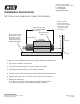
Installation Instructions
VC Precision Hydraulic Feed Controllers