Owner’s Manual Parts Manual Service Manual 150 2R ACE-Maxxam-002-03-2007
FOREWORD Thank you for purchasing an A.C.E. kart. We hope you will enjoy it. Before you begin operating the kart, please carefully read this Owner's Manual as it contains important safety and maintenance information. Failure to follow the warnings contained in this manual could result in serious injury or death. Be sure to follow the recommended maintenance schedule and service your kart accordingly. Preventive maintenance is extremely important to the longevity of your kart.
INDEX OWNER' S MANUAL Page 1. WARRANTY-------------------------------------------------------------------------------------------------------------------- 1 2. WARRANTY REGISTRATION FORM ---------------------------------------------------------------------------------3 3. ABOUT SAFETY ------------------------------------------------------------------------------------------------------------ 4 4.
INDEX SERVICE MANUAL Page 1. GENERAL INFORMATION ----------------------------------------------------------------------------------------------- 1 2. PERIODIC MAINTENANCEAND TUNE-UP PROCEDURES ----------------------------------------------------- 5 3. ENGINE -------------------------------------------------------------------------------------------------------------------------- 9 4. LUBRICATION SYSTEM INSPECTIONAND SERVICING -------------------------------------------------------- 24 5.
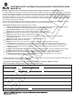
WARRANTY . . . A.C.E. SPORTS KARTS LIMITED WARRANTIES REGISTRATION ALL UNITS MUST BE REGISTERED WITHIN 10 DAYS OF PURCHASE OR THE WARRANTY IS VOID To register your product, complete the Warranty Registration form. Fax or mail the warranty registration form with a copy of the sales receipt to A.C.E. Sports. A warranty registration form MUST be on file with A.C.E. Sports before a warranty claim can be processed. All warranty work must be performed by an authorized dealer or service center.
WARRANTY PARTS NOT COVERED This warranty does not cover consumable wear and tear items such as, but not limited to: Throttle cable Brake cable Chains Seats Fasteners Air Filters Brake pads Tires Oil changes Problem occurring due to lack of proper maintenance Problem occurring due to abuse Modifications to your Maxxam that are not A.C.E.Sport approved will void the warranty. Defective parts are subject to recall by A.C.E.
. . . CUSTOMER SAFETY INFORMATION AND WARRANTY REGISTRATIN FORM MAXXAM 150 Warranty registration must be filed with A.C.E. Sports within 10 days of purchase or warranty will be void. In order to validate the warranty, purchaser agrees and promises to hold A.C.E.
ABOUT SAFETY In order to keep everyone safe, you must take responsibility for the safe operation of your kart. To help you make informed decisions about safety, we have provided operating procedures and other information on labels and in this manual. This information alerts you to potential hazards that could hurt you or others. It is not practical or possible to warn you about all the hazards associated with operating or maintaining a kart. You must use your own good judgment.
IMPORTANT SAFETY INFORMATION Your kart will provide you with many years of service and pleasure, provided you take responsibility for your own safety and understand the challenges you may meet while driving. There is much that you can do to protect yourself while operating your kart. You'll find many helpful recommendations throughout this manual. The following are a few that we consider most important. Follow the Age Recommendation Adult Supervision should be present for all operators under the age of 16.
IMPORTANT SAFETY INFORMATION Drive within Your Limits Pushing limits is another major cause of kart accidents. Never drive beyond your personal abilities or faster than conditions warrant. Remember that alcohol, drugs, fatigue, or inattention can significantly reduce your ability to make good judgments and drive safely. Alcohol, Drugs, and Driving Alcohol, drugs and driving don't mix.
SAFETY LABELS This section presents some of the most important information and recommendations to help you drive your kart safely. Please take a few moments to read these pages. The labels should be considered permanent parts of the kart. If a label comes off or becomes hard to read, contact your dealer for warning label replacements.
ARE YOU READY TO DRIVE ? Before each drive, make sure you and your kart are both ready to drive. This section discusses how to evaluate your driving readiness, what items you should check on your kart, and adjustments to make for your comfort, convenience, or safety. Before you drive your kart for the first time, we urge you to: Read this owner's manual and the labels on your kart carefully. Make sure you understand all the safety messages. Know how to operate all the controls.
ARE YOU READY TO DRIVE? Additional Driving Gear In addition to a helmet and eye protection, we also recommend: Sturdy off-road motorcycle boots to help protect your feet, ankles, and lower legs. Off-road motorcycle gloves to help protect your hands. Driving pants with knee and hip pads, a driving jersey with padded elbows, and a chest/ shoulder protector. Driver Training Developing your driving skills is an ongoing process.
IS YOUR VEHICLE READY TO DRIVE? Before each drive, it is important to inspect your kart and make sure any problems you find are corrected. A pre-drive inspection is a must, not only for safety, but because having a breakdown, or even a flat tire, can be a major inconvenience. If your kart has overturned or has been involved in a collision, do not drive it until your kart has been inspected by your dealer. There may be damages or other problems you cannot see.
IS YOUR VEHICLE READY TO DRIVE? Leaks, Loose Parts Walk around your kart and look for anything that appears unusual, such as a leak or loose cable. Lights Make sure the headlights, brake light and tail light are working properly. Throttle Check the freeplay and adjust if needed. Press the throttle to make sure it moves smoothly without sticking, and snaps back automatically when it is released. Brakes Press the rear brake pedal several times, check for proper brake pedal freeplay.
SAFE DRIVING PRECAUTIONS Off-Road Use Only Your kart and its tires are designed and manufactured for off-road use only, not for pavement. Driving on pavement can affect handling and control. You should not drive your kart on pavement. WARNING Operating this kart on paved surfaces may seriously affect handling and control of the kart, and may cause the vehicle to go out of control. Never operate the kart on any paved surfaces, including sidewalks, driveways, parking lots and streets.
SAFE DRIVING PRECAUTIONS Control Speed Driving at excessive speeds increases the chance of an accident. In choosing a proper speed, you need to consider the capability of your kart, the terrain, visibility and other operating conditions, plus your own skills and experience. WARNING Operating this kart at excessive speeds increases your chances of losing control of the kart, which can result in an accident.
SPECIFICATIONS DIMENSIONS Overall Length ------------------------------------------------------------------------------- 85 in. (2160mm) Overall Width -------------------------------------------------------------------------------- 53 in. (1346mm) Overall Height ----------------------------------------------------------------------------- 57.4 in. (1458mm) Wheelbase ----------------------------------------------------------------------------------- 59 in.
SPECIFICATIONS Brake Track --------------------------------------------------------------------------------- < 7 m@20miles/h Top Speed ------------------------------------------------- 30 miles/h (or limited as customers require) CHASSIS Front, Rear Brake --------------------------------------------------------- Hydraulic disc, left foot control Front Tire ------------------------------------------------------------------------------------------------- 20 x 7-8 Rear Tire -----------------------------------
OPERATION A. Operation controls WARNING - Do not attempt to start or operate the engine until you are completely familiar with the location and use of each control necessary to operate this vehicle. The operator must know how to stop this machine before starting and driving it. a. Throttle The right foot pedal is the throttle that controls the kart speed. As the engine speed increases above idle, the clutch automatically engages and moves the vehicle forward.
OPERATION B. Pre-Drive Inspection WARNING Perform this pre-drive inspection everyday before driving vehicle. If not performed, serious damage to the vehicle or personal injury may result. a. Check engine oil level. Check for leaks, add oil if required. b. Check fuel level. Add fuel as necessary and do not overfill. Check for leaks. c. Check brakes. Depress the rear brake pedal several times, then check for proper brake pedal freeplay. Make sure there is no brake fluid leakage. Adjust if necessary. d.
OPERATION Component locations MIRROR 0,5525 6($7 %(/7 67((5,1* :+((/ )/$* 32/( %5$&.(7 5($5 &$5*2 5$&. 72: %$// 7$1. &203 )8(/ )8(/ 7$1.
OPERATION C. Passengers The vehicle allows for two riders only. Combined maximum weight of driver and the passenger should not exceed 180kg or 400lbs. D. Seat Adjustment The seat must always be securely fastened in the position which best affords the operator control of the foot pedals, steering wheel, and the remote stop button. a. Pull seat adjustment handle upward to disengage seat slide. b. Move seat to desired position. c.
OPERATION/SERVICE INSTRUCTIONS F. Starting And Operating Instructions a. Before starting the engine, be sure that the driver is seated properly in the kart with the seat belt. b. Test the kart in an open space at the beginning to learn how to start, turn and stop. c. Operate the kart slowly until you are familiar with it. d. The turning radius of this kart is small and agile, so the centrifugal force is very high when turning at high speed.
SERVICE INSTRUCTIONS B. Engine Lubrication You must change the oil in the crankcase after the first 5 hours of operating your new engine (see Fig. 7) and after 10 hours of use thereafter. This will insure proper lubrication of internal parts and prevent costly repairs due to excessive wear. :$51,1* WARNING Used oil must be disposed of at a proper collection center a. Remove drain plug located on the right rear side of engine.
SERVICE INSTRUCTIONS D. Carburetor Adjustment Never make unnecessary adjustments. The factory recommended settings are correct for most applications. a. Warm up the engine (5~10min) b. Tighten the air screw gently. Backout 2-3/8 turns counter clockwise. c. Connect the tachometer, adjust the throttle to limit the idle speed. The standard value is 1400RPM. d. Turn the air screw counter clockwise slowly and observe the RPM of the engine, stop adjusting as the RPM reaches the top speed. e.
SERVICE INSTRUCTIONS H. Chain Adjustment Check the chain adjustment after the first two hours of use. Readjust if it has more than 1/2” flex. a. Loosen Nut #1. b. Adjust Nut #2. Turn Nut #2 clockwise in 1/2 turn increments, then turn nut #1 until tight. Follow this procedure until chain is at proper tension (see Fig. 10). c. Repeat the above two steps until chain is adjusted to desired fit. I. Adjustment of Front And Rear Shocks There are five adjustable positions on each shock.
REPAIR A. Front Wheel Replacement Do not disassemble the castle nuts when you replace the front wheels. It is only necessary to remove the four (4) lug nuts to remove the wheel. (See Fig. 12) Tighten the nuts after replacing the wheels. Figure 12 B. Rear Wheel Replacement Do not disassemble the castle nuts when you replace the rear wheels and hub assembly. Remove the cotter pin and the 24mm nut. Then slide off wheel and hub assembly.
REPAIR C. Front Wheel Alignment a. The front wheels should have a “toe-in” from 1/8” to 1/4”. To check for alignment, measure distance A and B between the centerline (CL) of the wheels. The proper toe-in dimension A should be 1/8” – 1/4” greater than dimension B. b. To adjust the alignments, loosen the lock nuts on both sides of Front Tie Rods. To make Dimension B smaller, turn the rod to the left. Adjust the rod to the right direction to make Dimension B larger.
PERIODICAL CHECK AND SERVICES The maintenance intervals in the following table are based upon average driving conditions. Driving in unusually dusty areas requires more frequent servicing.
27 left headlight 12V 35W cigar lighter 12V 72W lgnition/start SW LAMP SW emergency stop right headlight 12V 35W R B G B W G L L G B/Y G L brake SW B G/Y W B Y/R SB White w Gray GR R Low green LG O G Sky blue Green Red BR L Orange P Blue B Pink G Yellow Y Brown Black G/W main relay colour/sign table B/Y G G/W battery YTX9-BS CDI L/W B/YB/W R B/R Fuse 2*15A G grounding Y R REG G P R R grounding G G B/R Y/R starting motor P generator G R Y L/W st
INITIAL ASSEMBLY INSTRUCTIONS TOOLS NEEDED Floor jack 8mm wrench 14mm socket/extension 24mm socket/extension Needle nose pliers 10mm wrench/socket 17mm wrench/socket Protective gloves 12mm wrench/socket 19mm wrench/socket 1. LIFT THE KART In order to assemble the front suspension and steering, the front of the kart must be lifted high enough to install the front tires. We recommend that two people lift the front of the kart while a third person places a rear tire underneath. 2.
INITIAL ASSEMBLY INSTRUCTIONS 4. FRONT TIRES A. Remove lug nuts from front hub. B. Place tire in position by aligning the holes in the wheel with the lugs. C. Tighten lug nuts with 14mm socket with extension. D. Perform this same procedure on both left and right sides. 5 CARGO RACK A. Position the rack so that the inserted ends align with the holes in the frame behind the seat. Tighten with 10mm wrench/socket. B.
INITIAL ASSEMBLY INSTRUCTIONS 7. REAR TIRE A. Slide rear wheel/hub assembly onto axle. Splines must be aligned in order for the assembly to properly fit. B. Place small washer, then large washer on axle Tighten castle nut with 24mm socket with extension. C. Lock with cotter pin and needle nose pliers D Perform this same procedure on both left and right sides 8. BRUSH BARS A. Place main bars in proper location by putting the open ends over the bar mounts located on the frame. B.
INITIAL ASSEMBLY INSTRUCTIONS 9 WHEEL CAP Place one rubber wheel cap on each wheel. 10. STEERING WHEEL Place the steering wheel on mount, align the holes and tighten with 10mm wrench/socket. Snap steering wheel cap into place. 11 FENDERS A. Install front fenders by inserting the turned down stud of the fender mount into the fender sleeve on the frame. B. Insert provided bolt into the mounting hole and tighten the fender to the frame with 8mm and 10mm wrench. C.
INITIAL ASSEMBLY INSTRUCTIONS 13. BATTERY A. Put on protective gloves. B. Remove strip covering acid ports from battery C. Place funnel into acid ports on battery. With funnel aligned in battery press acid container firmly into funnel allowing the acid to flow into the battery. D. Allow all acid to drain from container. E. let the battery sit with cap off for 10 minutes. F.
239 County Road 4435 Brundidge, AL 36081 www.acesportsonline.
PARTS MANUAL COMPONENT LOCATIONS ( % + & ' * ) 4 0 - 2 .
10 13 22 15 21 23 8 20 13 25 22 30 19 21 18 20 30 19 2 24 29 27 17 26 14 7 4 11 9 12 4 5 6 4 11 14 1 16 3 FIG.
MAXXAM PARTS MANUAL Fig.1 CYLINDER HEAD ASSEMBLY REF. PART NO.
FIG.2 CYLINDER ASSEMBLY 9 9 7 6 5 3 4 1 2 8 Fig.2 CYLINDER ASSEMBLY REF. DESCRIPTION PART NO. QTY 1 513-1013 Cylinder Body Comp 1 2 513-1014 Cylinder Gasket 1 3 500-1305 Washer Sealing M06 1 4 500-1002 Dowel Pin M10x16 2 5 500-1009 Flange Bolt M06x12-ZN.
FIG.3 CRANKCASE ASSEMBLY (1) 11 16 8 10 6 11 18 2 7 12 15 14 4 1 5 13 17 9 13 3 13 Fig.3 CRANKCASE ASSEMBLY(1) REF. PART NO. DESCRIPTION QTY 1 513-2015 R Crankcase Cover Comp 1 2 513-1019 Crankcase Cover Gasket 1 3 500-1015 Cap Tappet Adjusting Hole 1 4 513-1020 Oil Filtering Screen 1 5 557-1003 Oil Filtering Spring 1 6 513-1021 Oil Level Stick 1 7 513-1083 AC Generator Cord Clamper 1 8 513-1022 Oil Seal 19.8x30x5 1 9 513-1074 O-Ring 30.
6 6 6 7 6 7 7 8 7 8 9 9 11 15 23 2 11 1 3 25 4 11 24 12 21 20 2 27 11 16 22 5 26 14 18 11 13 28 28 10 17 11 6 19 28 19 FIG.
MAXXAM PARTS MANUAL Fig.4 CRANKCASE ASSEMBLY(2) REF. PART No. DESCRIPTION QTY 1 513-2013 R Crankcase Assy 1 2 513-1024 Engine Hanger Rubber Bushing 2 3 513-1025 Crankcase Gasket 1 4 13- L. Crankcase Assy 1 5 513-1026 Bushing RR Cushion Under Rubber 1 6 500-1004 Flange Lock Nut M08 5 7 500-1052 Washer M08 4 8 500-1053 Stud Bolt M08x187.5 2 9 500-1030 Stud Bolt M08x195.
FIG.5 CRANKSHAFT CONROD & PISTON ASSEMBLY 13 2 10 3 4 5 11 12 10 1 9 6 7 8 Fig.5 CRANKSHAFT CONROD & PISTON ASSEMBLY REF. DESCRIPTION PART NO.
FIG.6 CAMSHAFT ASSEMBLY 10 1 9 2 9 8 3 1 4 2 5 3 6 7 Fig.6 CAMSHAFT ASSEMBLY REF. DESCRIPTION PART NO.
FIG.7 LEFT COVER ASSEMBLY 9 7 8 2 7 8 2 3 1 1 3 8 3 6 8 5 56 6 5 5 5 5 5 5 5 5 7 Fig.7 LEFT COVER ASSEMBLY REF. PART NO. DESCRIPTION QTY 1 540-1006 L Cover 1 2 513-1040 L Cover Gasket 1 3 500-1060 Screw ST 4.
FIG.8 FAN COVER AND SHROUD ASSEMBLY 3 7 11 10 13 2 66 13 6 9 8 9 9 1 10 10 14 5 4 Fig.8 FAN COVER AND SHROUD ASSEMBLY REF. PART NO. 1 513-1043 Fan Cover Comp 1 2 513-2010 Starter Cable Clamper 1 3 513-2011 Cooling Duct 1 4 513-3014 Lower Shroud 1 5 513-1078 Lower Shroud Seal 1 6 513-3015 Upper Shroud Comp 1 7 513-3022 High Tension Cord Clip 1 8 513-1079 Upper Shroud Seal 1 9 500-1062 Screw ST 4.
FIG.9 OIL PUMP ASSEMBLY 5 4 4 2 3 1 Fig.9 OIL PUMP ASSEMBLY REF. DESCRIPTION PART NO.
FIG.10 DRIVEN PULLEY AND CLUTCH SUBASSEMBLY 1 3 2 Fig.10 DRIVEN PULLEY AND CLUTCH SUBASSEMBLY REF. PART NO.
FIG.11 11 TRANSMISSION ASSEMBLY 3 10 2 1 5 4 6 9 12 8 7 15 14 13 6 Fig.11 TRANSMISSION ASSEMBLY REF. 1 2 3 4 5 6 7 8 9 9. 10 11 12 12. 13 14 15 DESCRIPTION PART NO.
FIG.12 ELECTRIC SYSTEM 1 2 4 3 Fig.12 ELECTRIC SYSTEM REF. DESCRIPTION PART NO. QTY 1 513-2005 Stator Comp-8 pose 1.1 513-1053 Stator Comp-6 pose 2 513-1054 Flywheel Comp-8 pose 2.
FIG.13 ELECTRIC STARTER ASSEMBLY 5 4 1 2 6 3 Fig.13 ELECTRIC STARTER ASSEMBLY REF. 1 2 3 4 5 6 PART NO. DESCRIPTION QTY 513-1056 Flange Starting Clutch 1 513-1090 Starter Reduction Gear Shaft 1 513-1058 Reduction Gear 1 500-5302 Flange Bolt M06x16 2 513-1059 Starter Motor Assy 1 613-0021 O-Ring 24.0x3.
FIG14 DRIVE PULLEY SUBASSEMBLY 1 Fig.14 DRIVE PULLEY SUBASSEMBLY REF. PART NO.
7 10 20 13 12 1 17 25 14 23 20 9 11 2 29 16 30 27 6 1 25 5 31 1 19 21 26 1 15 1 22 3 8 1 26 4 24 22 28 18 FIG.
MAXXAM PARTS MANUAL Fig.15 CARBURETOR REF. PART NO.
FIG.16 24 FRAME GROUP 41 36 37 25 38 2 2 1 7 26 6 7 27 28 7 6 7 4 35 13 6 42 33 19 14 10 11 VIN No.
MAXXAM PARTS MANUAL Fig.16 FRAME GROUP REF. PART NO.
FIG.
MAXXAM PARTS MANUAL Fig.17 STEERING SHAFT ASSEMBLY REF. PART NO.
31 15 33 34 12 1 35 36 40 30 2 37 26 26 3 30 32 4 40 7 40 5 40 26 6 11 10 9 8 7 39 13 17 18 19 20 21 16 15 22 24 25 23 27 38 28 29 14 FIG.
MAXXAM PARTS MANUAL Fig.18 SUSPENSION ARM ASSEMBLY REF. DESCRIPTION PART NO.
FIG.19 REAR CARGO RACK/SEAT/BELT 1 2 3 14 21 4 21 14 27 7.1 12 5 6 8 11 9 7.
MAXXAM PARTS MANUAL Fig.19 REAR CARGO RACK/SEAT/BELT REF. DESCRIPTION PART NO. QTY 1 509-3021 Tail Light Bulb 21w/5w -12v 1 2 609-0004 Tail Light - (K30-50) long wire 95 1 3 500-1031 Lock Nut M06 2 4 634-0001 Rear Cargo Rack (Blue) 1 4 634-0002 Rear Cargo Rack (Yellow) 1 4 634-0003 Rear Cargo Rack (Red) 1 5 600-0009 Flange Bolt M08x16-color 4 6 600-2303 Flange Lock Nut M08-black 10 7 699-0101 Rack Support Arm L. (Blue) 2 7 699-0201 Rack Support Arm L.
FIG.
MAXXAM PARTS MANUAL Fig.20 ENGINE/MUFFLER/AIR CLEANER REF. 1 2 3 4 5 6 7 8 9 10 11 12 13 14 15 16 17 18 19 20 21 22 23 24 25 26 27 28 29 30 31 32 33 34 35 36 37 38 39 40 41 42 43 DESCRIPTION PART NO.
FIG.
MAXXAM PARTS MANUAL Fig.21 REAR SWING ARM REF. 1 2 3 4 5 6 7 8 9 10 11 12 13 14 15 16 17 18 19 20 21 22 23 24 25 26 27 28 29 30 31 32 33 34 35 36 37 38.1 38.2 39 40 41 42 43 44 45 46 47 48 49 50 51 52 53 PART NO.
1 2 3 3 4 5 16 6 7 8 25 3 9 17 10 11 13 14 12 15 24 19 18 20 21 22 23 FIG.
MAXXAM PARTS MANUAL Fig.22 REAR HOUSING REF. DESCRIPTION PART NO.
FIG.
MAXXAM PARTS MANUAL Fig.23 WIRE HARNESS/ELECTRICAL DESCRIPTION REF. PART NO. 1 609-0003 Wire Harness 1 2 500-1076 Lock Nut M05 2 3 509-3035 Switch Panel Cover 1 4 500-1066 Pan Screw M05X12 4 5 509-3036 Power Outlet 1 6 609-0015 Wire Harness tie wrap 10 7 609-0005 Key Switch 1 8 609-0006 Engine Stop Button 1 9 609-0016 Light Switch 1 10 500-5302 Flange Bolt M06x16 1 11 500-1031 Lock Nut M06 3 12 609-2830 Regulate Rectifier Comp 1 13 509-1007 C.D.I.
FIG.24 REVERSE ASSY.
MAXXAM PARTS MANUAL Fig.24 REVERSE ASSEMBLY REF. DESCRIPTION PART NO. QTY 1 639-0003 Gear Case. R 1 2 639-0004 Gear Case.
FIG.25 2 3 TOOL KIT 6 4 5 7 8 9 10 1 Fig.25 TOOL KIT REF. PART NO.
FIG.26 PARKING STICKER 2 1 WARNING 3031112 Moving parts can crush and cut. Keep hands clear. Do not operate with guard removed. 12 MAXXAM REVERSE LEVER PARKING BRAKE 150 2R 3 5 WARNING 4 NO RIDING THIS GO-KART CAN BE HAZARDOUS TO OPERATE if driven carelessly. LONG NO WARNING WARNING INJURIES can result if you do not follow these instructions: 6 READ OWNER'S MANUAL AND ALL LABELS BEFORE YOU OPERATE THIS GO-KART. WARNING NEVER OPERATE THIS GO-KART WITHOUT PROPER INSTRUCTIONS.
A.C.E. SPORTS LLC . . . 239 County Road 4435 Brundidge. AL 36010 Phone: 1-888-562-9 ACE Fax: 1-888-562-8 ACE www.acesportsonline.