OPERATOR’S BOOKLET HEAVY DUTY PORTABLE DRY SODA BLASTER MODEL 2-PS MADE IN USA
ACE MODEL 2-PS QUICK SET UP GUIDE 1. Connect the Model 2-PS to your compressor, using an air supply line of at least ½” I.D (Internal Diameter). If you are using an air supply line longer than 30 ft., or with an air compressor greater than 30 cfm, use a ¾” I.D. air supply line with a reducer to thread into the ½” NPT (National Pipe Thread) air inlet valve on the front of the Model 2-PS. 2. DO NOT USE a plug in male/female type quick disconnect on your air supply line.
ACE MODEL 2-PS QUICK TROUBLE SHOOTING GUIDE In the event that you encounter an issue with your ACE Model 2-PS, listed below are some quick solutions to get you up and running again. are a special rubber composition for maximum tube life and machine performance. 4. If you are getting a lot of water in the bowl of the adjustable pressure regulator, you are probably getting water in the tank. Moisture is the main cause of clogging in any soda blaster.
IMPORTANT INFORMATION CONCERNING PLANTS & GRASS The information below is provided courtesy of the ARMEX website: To minimize damage: • Soak the soil and leaves thoroughly before blasting. It is best to use a sprinkler for 4-6 hours to completely soak the soil, leaves, and branches before blasting. ® Will ARMEX damage plants or grass? One biological process that can be disturbed by the presence of any free sodium ion, including sodium bicarbonate is the process of photosynthesis.
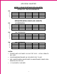
ACE SODA BLASTER MODEL 2-PS HD PORTABLE SODA BLASTER ESTIMATED CFM REQUIREMENTS PSI 90 80 60 40 13 12 10 7 3/32” 19 18 15 10 1/8” 29 27 23 18 5/32” +36 34 30 23 3/16” +50 +45 35 32 ¼” ESTIMATED MEDIA USAGE (LBS / MINUTE) PSI 90 80 60 40 1/8” RESTRICTOR .51 .92 .46 .88 .37 .78 .28 .55 3/32” 1/8” 1.47 1.38 1.20 .97 5/32” 2.21 1.70 1.57 1.34 3/16” 4.04 3.25 2.62 2.52 ¼” PSI 90 80 60 40 7/64” RESTRICTOR .32 .58 .29 .55 .27 .53 .26 .50 3/32” 1/8” .93 .92 .90 .88 5/32” 1.39 1.33 1.26 1.21 3/16” 2.
ACE SODA BLASTING MODEL 2-PS AND MODEL 2-S PERFORMANCE TIPS • We have been finding soda “clumps” in new bags of soda blast media from the factory. These clumps will clog the restrictor in the Model 2-PS and 2-S, and the down tubes in the Performance Plus. We recommend that you screen your soda through a piece of 1/16” mesh into a bucket, and then fill your soda blaster. This will save you time in the long run, and also increase the life of the tubes inside of your control box on the Model 2-PS and 2-S.
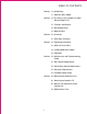
TABLE OF CONTENTS Section 1.0 Introduction 1.1 Soda Dry Blast Media Section 2.0 The Heavy Duty Portable Dry Soda Blaster Model 2-PS 2.1 Features and Benefits 2.2 Site Requirements 2.3 Specifications Section 3.0 Assembly 3.1 Start-Up Instructions Section 4.0 Operating Procedures 4.1 Safe Use Instructions 4.2 Loading Soda Blast Media 4.3 Operation Section 5.0 Maintenance and Troubleshooting Guide 5.1 Blast Nozzle Replacement 5.2 Water Spray Nozzle Replacement 5.3 Restrictor Replacement 5.
1.0 Introduction abrasive flow rate and velocity for efficient operation. The Model 2-PS is a fully portable system that includes bump hat and operator hood to protect the operator from dust and other contaminants. Air safety lock out, ceramic nozzle assembly, and water nozzle for spray off and dust reduction, provide the operator with clear vision of the abrasive cleaning process.
• Remote Blast Control - Automatic Shut-off if Handle Pressure is Released - Control at Nozzle Handle - System Shuts Off at the Tank • Blast Hood with Bump Cap (included)Added Safety Protection for the Operator • Contains Features Usually Available Only on More Expensive Models • Pressure Vessel: ASME Code • Working Pressure-Range: 30 to 120 PSI • Compressed Air Minimum: 80 PSI @ 18 CFM • Soda Blast Media Capacity: 100 Lbs. Dry Blast 3.
2.Connect unit to a source of clean water 30-90 PSI (optional). 5. WEAR BUMP HAT AND HOOD AT ALL TIMES WHILE OPERATING. 6. WEAR GLOVES AT ALL TIMES WHILE OPERATING. 7. WARNING: ALWAYS POINT NOZZLE AWAY FROM SELF AND OTHERS. Press the hand operated LEVER to start the flow of air. * Verify that the System is Operational Once the system is fully assembled, check to make sure it is operational and ready to use: 1. Make sure that the pressure vessel vent valve is closed. 8.
1. Keep this Operator's Booklet with the equipment to allow easy access for reference by operators. 2. ALWAYS WEAR PROTECTIVE SAFETY GEAR-SAFETY GLASSES / FACE SHIELD, HOOD, APPROVED GLOVES, RESPIRATOR, EAR PROTECTION AND APPROPRIATE CLOTHING. 3. ARMS, LEGS AND BODY TO BE COVERED WITH PROTECTIVE CLOTHING, INCLUDING STURDY LEATHER BOOTS. 4. Do NOT operate any electrical equipment near the unit. 5. Do NOT smoke, eat, or drink while blasting. 6. Do NOT spray aerosols near the unit. 7.
6. NOTE: USE SODA BLAST MEDIA ONLY. USE OF OTHER MEDIA TYPES WILL VOID ALL WARRANTIES AND COULD CAUSE PERSONAL INJURY! 7. Remove funnel and REPLACE SAFTEY CAP onto the pressure vessel media inlet fitting. Making sure it is tightly secured. 8. Shut ball valve on vacuum inlet by turning 90 degrees from inlet. (closed) 2. Vent the pressurized air from the delivery unit using the vessel valve located on the top of the pressure vessel unit. Turn valve slowly (earplugs recommended) releasing air pressure. 3.
4. Wearing proper safety gloves, hold the nozzle/hose assembly at a 45-degree angle, within 6-18”inches of the surface to be cleaned. Grasp the water ball valve and hose with the other hand. ALWAYS KEEP TWO HANDS ON THE BLASTING HOSE. stop the flow of media to the nozzle and water spray. TURN THE SAFETY LOCK OUT VALVE TO THE OFF POSITION BEFORE SETTING THE BLAST NOZZLE HANDLE ON TO THE PORTABLE SODA BLASTER. 8. DO NOT DROP THE NOZZLE HANDLE END OF THE BLASTER, AS DAMAGE TO THE NOZZLE TIP MAY RESULT. 5.
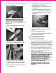
7. Unscrew the blast nozzle hold down nut, making sure not to lose or displace washer. 4. Vent the pressurized air from the delivery unit using the vessel valve located on the top of the pressure vessel unit. Turn valve slowly (earplugs recommended) releasing air pressure. 8. Gently tap the blast nozzle until it separates from the hold down nut. 5. Lay nozzle handle on work surface. Remove the first three (3) 2” Velcro straps from the handle, noting the position for replacing. 9. Replace nozzle.
nozzle disc. Align nozzle to make a triangular cone pattern. 3. Disconnect unit from compressed air source. 4. Vent the pressurized air from the delivery unit using the vessel valve located on the top of the pressure vessel unit. Turn valve slowly (earplugs recommended) releasing air pressure. 5.3 Restrictor Replacement 1. Turn off the safety lockout air valve located at the front of the pressure vessel and lock it out. (sideway position) 5. Lay nozzle handle on work surface.
DISCONNECT UNIT FROM COMPRESSED AIR SUPPLY. pliers, remove the factory installed 1/8” restrictor, noting the orientation. 3. Using a medium sized pipe wrench, loosen the union pipefitting that attaches the control unit to the bottom of the pressure vessel. 6. Replace restrictor. Reverse steps to reconnect control unit to bottom of the pressure vessel. 4.
5.4 Troubleshooting Guide PROBLEM INDICATIONS REMEDY No air at nozzle Air line hook-up Safety lock out off Hand lever not depressed Regulator setting Cylinder on control unit not working Plugged nozzle Plugged shut off tube Control unit adjustment Nozzle handle valve Check compressor, air line, and power. Turn safety lock out handle to on position Check for obstruction under lever. Adjust regulator setting. Check red and black control tubes for leaks or kinks. Remove nozzle; clean or replace nozzle.
6.0 Servicing the Soda Blast Unit 1. Inspect all components (hoses, nozzles, etc.) for wear and damage. Replace as required. 2. Inspect all controls (tubing, hand operated lever, water ball valve, etc.) for damage and wear. This section covers the routine servicing of the Model 2-PS. 6.1 Servicing the Model 2-PS Turn off the safety lockout air valve located at the front of the pressure vessel and lock it out. (side ways position) TEST unit to ensure proper operation. 6.
TO ADJUST EQUALLY WILL DAMAGE THE CONTROL UNIT. TURN OFF THE SOURCE OF COMPRESSED AIR TO THE UNIT. 2. After each complete revolution of the two (2) adjustment bolts, test to see if the blast nozzle shuts off completely. 2. Vent the pressurized air from the delivery unit using the vessel valve located on the top of the pressure vessel unit. Turn valve slowly (earplugs recommended) releasing air pressure. 3.
4. With your free hand placed under the control unit (so as to not let it drop), completely unscrew the union, allowing the control unit to separate from the pressure vessel (place a small container under the pressure vessel to catch any remaining soda). 7. Disconnect the large air supply hose (top of control unit) by loosening hose clamp (slide clamp up onto hose). 8. Disconnect the large blast nozzle feed hose (bottom of control unit) by loosening hose clamp (slide clamp up onto hose). 5.
bolts and washer aside noting placement. 13. Using a 5/16” socket wrench with extension, loosen the (4) hose clamps on the (2) control tubes (note position of hose clamp bolts). Use a flat head screwdriver to gently pry one end of the control tube off of the barbed fitting. Gently rotate, while pulling, to remove the control tube from the other end (repeat for other tube).
15. Reassemble the control unit, using the following steps. Slide (2) hose clamps onto each control tube. Slide one end onto a barbed nipple in the control housing, and the other end on the barbed nipple directly across from first nipple. MAKE SURE HOSE CLAMP BOLTS ARE ON THE SIDE CLOSEST TO THE CENTER OF HOUSING. Repeat for other control tube. Slide clamps to end of each tube and tighten securely with 5/16” socket wrench with extension. 17.
weld nuts but from the flat top surface of the spring plate. This is the standard factory setting). 21. Attach control unit to the bottom of the pressure vessel. MAKE SURE THAT THE UNION THREADS ARE FREE OF SODA AND SEATED COMPLETELY. 19. Replace control unit cover with the (4) hex bolts (washers against bolt heads). 22. Reconnect all air feed and blast hoses to the proper fittings. Tighten clamps. WARNING: NEVER OPERATE OR ADJUST THE CONTROL UNIT WITH THE CONTROL UNIT COVER OFF.
6.
23 HOSE NIPPLE 1/2" NPT #413421 SPRING COMPRESSION #411604 PIPE UNION 1/2" NPT #411322 MANIFOLD #411388 Manifold #411388 has replaced the elbow, nipple and pipe ELBOW 90 1/2" NPT #411166 DRW.50 CONTROL BOX SODA BLASTER ELBOW 90 #411170 AIR CYLINDER #410411 HOSE CLAMP #413406 RESTRICTOR 1/8" STD.
DRW.
25
Automotive Cleaning Equipment 421013 401 N. Griffin, Grand Haven, Michigan 49417 888.772.3263 616.844.9243 Fax ace-sandblasting.