User’s Manual Wireless 11n AP/Router (1T2R & 2T2R) Brand: ACEEX Model No: NR22
Index Chapter 1 Introduction .............................................................................................................................. 5 1.1 Overview............................................................................................................................. 5 1.2 Features ............................................................................................................................... 5 1.3 System Requirements...............................................
.7.6 System Log .................................................................................................................... 48 3.8.1 TCP/IP Settings for Windows Operating System .......................................................... 49 Certification: FCC, CE .......................................................................................................................... 56 Appendix A Glossary .............................................................................................
FCC and Other Compliance Statements Federal Communication Commission Interference Statement This equipment has been tested and found to comply with the limits for a Class B digital device, pursuant to Part 15 of FCC Rules. These limits are designed to provide reasonable protection against harmful interference in a residential installation.
special attention must be paid to the dangers of electric shock and static electricity when working with electrical equipment. All guidelines of this and of the computer manufacture must therefore be allowed at all times to ensure the safe use of the equipment.
Chapter 1 Introduction Congratulations on your purchase of an Instant Wireless 11n Router for cable/xDSL application. The Wireless 11n Router is the perfect option to connect a small group of PCs to a high-speed Broadband Internet connection or to an Ethernet backbone. Configurable as a DHCP server, the Broadband Router acts as the only externally recognized Internet device on your local area network (LAN).
z Ethernet Interface ‧Compliant with IEEE 802.3 and 802.3u 10/100 Mbps z HTTP Web-Based Management ‧Firmware upgrade by UI ‧WAN and LAN side connection statistics ‧Advanced QoS ‧Password protected access ‧Wireless LAN ‧System log 1.
Chapter 2 Installation This chapter offers information about installing your router. If you are not familiar with the hardware or software parameters presented here, please consult your service provider for the values needed. 2.1 Checklist Check the shipping box carefully to ensure that the contents include the items you ordered. If any of the items are missing or damaged, contact your local distributor. The contents of your carton may vary depending on your service provider.
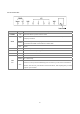
2.2 The Front LEDs LED State POWER ON ON WAN Flashing Description Press the button to power one the router. "Showtime"-successful connection between ADSL modem and telephone company's network. "Handshaking"-modem is trying to establish a connection to telco's network Modem is powered OFF ADSL Carrier Detect if LED is flash. OFF No link. PWR ON The router power on and running well. WLAN-Secure ON When wireless security encryption enable. WLAN-ACT Flashing Wireless LAN enable and link status.
2.3 The Rear Ports Connector POWER LAN (1-4) WAN WPS Description Power connector with 9VAC / 1Ampere. Router is successfully connected to a device through the corresponding port (1, 2, 3 or 4). If the LED is flashing, the Router is actively sending or receiving data over that port. The WAN (Wide Area Network) Port is where you will connect your cable, DSL modem or Ethernet backbone. Push button for WPS link. R/SMA Connector Antenna Connector. 2.
Chapter 3 Configuration 3.1 Determine your connection settings Before you configure the router; you need to know the connection information supplied by your service provider. 3.2 Connecting the Wireless 11n Router to your network Via Ethernet Cable to LAN Port and connect to your PC/NB RJ-45 Port or via wireless link to access the 11n router. 3.3 Configuring with Web Browser It is advisable to change the administrator password to safeguard the security of your network.
3.3.1 Wireless 11n Router Setting In AP/Router root page, user can change the language. Click Status, Statistic or Management can directly jump to the related pages.
3.3.2 Operation Mode Setting There are four operation modes can choose, Bridge, Gateway, Ethernet Converter or AP Client. Bridge : All Ethernet ports and wireless interfaces are bridged into a single bridge interface. The router will work as bridge only.. Gateway: The device work as wireless router. The NAT will can set as enable or disable, WAN port need to link to the Internet. User can enable/disable the NAT function.
3.4.1 WAN Setting There are 5 selections for WAN connection type, the detail information as follows.
STATIC(Fixed IP): If you need to assign static IP addresses to the devices in your network, please remember that the IP address for each computer or device must be in the same IP address range as all the devices in the network. Each device must also have the same subnet mask. For example: Assign the first computer an IP address of 192.168.1.2 and a subnet mask of 255.255.255.0, the second device an IP address of 192.168.1.3 and a subnet mask of 255.255.255.0, and so on.
DHCP(Auto config): It’s will auto get the IP address from the DHCP Server.. Assign the length of time for the IP lease, default setting is 86400 seconds. The Hostname is the name of the device.
PPPoE(ADSL): Username and Password: Fill in the User Name and Password that provided by your ISP. Verify Password: Retype the password to confirm. Operation Mode: Set the router as Keep Alive or On demand.
L2TP: Layer 2 Tunneling Protocol (L2TP), a tunneling protocol used to support virtual private networks (VPNs). Server IP Address: Fill in the L2TP Server IP address that provided by your Internet Service Provider (ISP). Username and Password: Fill in the User Name and Password that provided by your ISP. Address Mode: Select to use Static or Dynamic IP mode.
PPTP: Point-to-Point Tunneling Protocol (PPTP) is a method for implementing virtual private networks (VPNs). Server IP Address: Fill in the PPTP Server IP address that provided by your Internet Service Provider (ISP). Username and Password: Fill in the User Name and Password that provided by your ISP. Address Mode: Select to use Static or Dynamic IP mode.
3.4.2 LAN Setting To set up the configuration of LAN interface, private IP of your router LAN port and subnet mask for your LAN segment. Default IP is 192.168.0.1. IP Address: The IP of your Router LAN port (default 192.168.0.1). Subnet Mask: Subnet Mask of you LAN (default 255.255.255.0). All devices on the network must have the same subnet mask to communicate on the network. LAN2: Enable / Disable LAN 2. LAN2 IP: The IP address of LAN2. LAN2 Subnet Mask: Subnet Mask of LAN2.
20
3.4.3 DHCP Clients Setting The information of IP, MAC, address and expire time of the DHCP clients that have connected with this device.
3.4.4 Advanced Routing Setting Static Routing Settings User can set a route rule(table) in here.. Destination: The destination IP address. Range: Host/Net, when select “Net”, there is another “Netmask” column need to fill out. Gateway: The gateway for the routing. Interface: Via LAN/WAN or User can define by custom. Comment: Memo for the routing rule. Dynamic Routing Settings Use RIP to auto build the routing rule. User can enable the dynamic routing settings in here.
3.4.5 QoS Setting The QoS (Quality of Service) Settings page provides different priority to different users or data flows. Quality of Service: Enable/Disable the QoS, default setting is Disable. Upload Bandwidth: The parameter for upload bandwidth. Download Bandwidth: The parameter for download bandwidth. Please don’t forget to submit when you finish the setting.
3.5.1 Wireless-Basic Setting Radio Off: Enable/Disable the wireless. Network Mode: There are 3 mode can choose, 11/b/g/n mixed mode/11b only/11g only. SSID: set up the wireless ID, default is wireless. Multiple SSID 1 ~ 7: You can set up to four SSID for this wireless network. Broadcast Network Name(SSID): Enable/Disable the SSID broadcast. AP Isolation: Enable/Disable this function. Create a separate virtual network for your wireless network.
wireless network. MBSSID AP Isolation: Enable/Disable this function. BSSID: Displays the Basic Service Set Identity (BSSID) of this router. This parameter is the same as the MAC address of LAN port. WDS (Wireless Distribution System): WDS Mode: Default is Disable, there are 3 Mode can choose, Lazy Mode(Auto), Bridge Mode(Bridge Only) and Repeater Mode(AP + Bridge). Phy Mode: Select the option in the drop-down list to enable CCK, OFDM, HTMIX, or GREENFIELD mode for physical layer transceivers.
3.5.2 Advanced Setting Advanced Wireless: BG Protection Mode: Some 802.11g wireless adapters support 802.11g protections, which allows the adapter search for 802.11b/g singles only. Select “Auto” to turns it on or off automatically, select “On” to support protection or select “Off” to disable this function. Beacon Interval: Beacons are packets sent by an access point to synchronize a wireless network. Specify a beacon interval value. Default (100ms) is recommended.
multicast messages. Fragment Threshold: This value should remain at its default setting of 2346. If you experience a high packet error rate, you may slightly increase your fragmentation threshold within the value range of 0 to 2346. Setting the fragmentation threshold too low may result in poor performance. RTS Threshold: Request To Send threshold. This value should remain at its default setting of 2347.
Wi-Fi Multimedia: WMM Capable: This will enhance the data transfer performance of multimedia contents when they’re being transferred over wireless network. APSD Capable: Automatic Power saves Delivery. Select to enable / disable data flow using power saving mode during transmitting. DLS Capable: Enable/Disable this function. WMM Parameters: You can configure WMM parameters by clicking on the 28 button.
configuration window pops up (as shown below). Manually configure the parameters and click on the “Apply” button to execute. Multicast-to-Unicast: It can receives Multicast streams from the network backbone, converts them to Unicast format, and routes them to the set-top-boxes of end-users over the last mile infrastructure (e.g. DSL, Ethernet, WiFi).
3.5.3 Security Setting SSID Choice: Please choose a SSID you have set for this router in the Wireless Settings > Basic Settings from the drop-down list. The SSID will be shown on the wireless network for recognizing.. Security Mode: There are 10 modes for you to select: Open, Shared, WEP Auto, WPA, WPA-PSK, WPA2, WPA2-PSK, and WPA-PSKWPA2-PSK, WPA1WPA2, 802.1x. Please refer to the following description.
Security Mode -- Open / WEP Auto Default Key: Select to use the WEP key value of 1, 2, 3 or 4 as in the following settings. WEP Keys: Select ASCII or Hex to setup the key value. ASCII (American Standard Code for Information Interchange) is a code for representing English letters as numbers from 0-127. Hexadecimal digits consist of the numbers 0-9 and the letters A-F. Access Policy: Policy: Default is Disable, you can allow or Reject the wireless station.
Security Mode -- Shared Default Key: Select to use the WEP key value of 1, 2, 3 or 4 as in the following settings. WEP Keys: Select ASCII or Hex to setup the key value. ASCII (American Standard Code for Information Interchange) is a code for representing English letters as numbers from 0-127. Hexadecimal digits consist of the numbers 0-9 and the letters A-F. Access Policy: Policy: Default is Disable, you can allow or Reject the wireless station.
Security Mode -- WPA-PSK / WPA2-PSK / WPA-PSK + WPA2-PSK WPA Algorithms: Mark the option to enable modes of TKIP, AES, or TKIPAES (TKIPAES is only available in the security modes of WPA2-PSK and WPAPSK + WPA2-PSK) Pass Phrase: Enter a pass phrase encryption key format (8~32 bytes). Key Renewal Interval: Enter a value to setup the WPA key renewal interval. The device regenerates the key in every interval seconds that you have setup without disconnection.
Security Mode -- WPA / WPA2 / WPA1 + WPA2 / 802.1x WPA Algorithms: Mark the option to enable modes of TKIP, AES, or TKIPAES (TKIPAES is only available in the security modes of WPA2-PSK and WPAPSK + WPA2-PSK) Key Renewal Interval: Enter a value to setup the WPA key renewal interval. The device regenerates the key in every interval seconds that you have setup without disconnection. Radius Server: IP Address: Radius Server IP address. Port: The default port number is 1812.
3.5.4 WPS Setting The primary goal of Wi-Fi Protected Setup (Wi-Fi Simple Configuration) is to simplify the security setup and management of Wi-Fi networks. This Router supports the configuration setup using PIN configuration method or PBC configuration method through an internal or external Registrar. WPS: Enable/Disable the WPS. Default setting is disable. WPS Summary: Shows the information of WPS current status, configured, SSID, authentication mode, and pre-shared key.
3.5.5 Station List Monitor Stations which associated to this AP/Router here.
3.6.1 MAC/IP/Port Filtering Setting The Wireless Router could filter the outgoing packets for security or management consideration. You can set up the filter against the IP addresses to block specific internal users from accessing the Internet. The firewall could not only obstruct outside intruders from intruding your system, but also restricting the LAN users. Port filter restricts certain type of data packets from your LAN to Internet through the router.
MAC/IP/Port Filtering: Enable/Disable the function. Default Policy - The packet that don’t match with any rules would be: Dropped/Accepted. MAC/IP/Port Filtering Settings: MAC address: Fill out the MAC address that you wish to filter. Dest IP Address: Fill in the destination IP address that you wish to filter. Source IP Address: Fill in the source IP address that you wish to filter. Protocol: Select the protocol type of TCP, UDP or ICMP.
3.6.2 Port Forwarding Setting Virtual Server help redirect requests from computers on the LAN to a server set up on the LAN. You can setup an Internet service on the computer on local network, without exposing it on Internet directly. You can also build many sets of port redirection, to provide many different Internet services on different local computers via a single Internet IP address. Virtual Server Settings: Enable/Disable. IP Address: Fill in the IP of your LAN Server.
3.6.3 DMZ Setting The virtual DMZ (Demilitarized Zone) is used to enable protocols, which need to open ports on the router. The router will forward all unspecified incoming traffic to the host specified in this page. To configure it, mark to enable virtual DMZ and then enter the Host IP (private IP address) and click Apply to enact the setting.
3.6.4 System Security Settings Remote Management via WAN: Allow/Deny. Ping from WAN filter: Disable/Enable. Stateful Packet Inspection (SPI): Disable/Enable.
3.6.5 Content Filtering Settings User can set up content filter to restrict the importer content access. Webs Content Filter: Can filter Proxy/Java or ActiveX. Webs URL Filter Settings: Add a URL filter: Fill in the URL you want to filter. Webs Host Filter Settings Add a Host(Keyword) Filter: Fill in the keyword which you want to filter.
3.7.1 Management Settings Language Settings: Can select language which you want. Administrator Settings: Set the account and password to set and manage the Wireless Device. NTP Settings: Can set the NTP server here. Green AP: Can set the save mode for the device, set the duration and Wi-Fi Tx power. DDNS Settings: Dynamic DNS Provider: The website that provides DDNS service. Please select from the drop-down list. Account: DDNS login account.
3.7.2 System Log User can upgrade the firmware in this page. Be careful, don’t power off when doing the upgrade process.
3.7.3 Settings Management Users can Export Settings or Import Settings here. If want to load the factory defaults, please click the Load default button.
3.7.4 System Status You can check the device status in this page, The firmware version, Internet Configuration and LAN settings.
3.7.5 Statistic This page allows users to get information of data transferring condition, and monitor the status and performance of this router including interface, receiving/sending packets, and receiving/sending errors.
3.7.6 System Log This page shows the system log information.
3.8.1 TCP/IP Settings for Windows Operating System 1. How can I find my IP Address in Windows 95, 98, or Me? ‧Click on Start, then click on Run. ‧The Run Dialogue Box will appear. Type winipcfg in the window as shown then click OK ‧The IP Configuration window will appear, displaying your Ethernet Adapter Information. ‧Select your adapter from the drop down menu. ‧If you do not see your adapter in the drop down menu, your adapter is not properly installed.
2. How can I find my IP Address in Windows 2000/XP? ‧Click on Start and select Run. ‧Type cmd then click OK. ‧From the Command Prompt, enter ipconfig. It will return your IP Address, subnet mask, and default router. ‧Type exit to close the command prompt. ‧Make sure you take note of your computer´s Default Router IP Address. The Default Router is the IP Address of the router. By default, it should be 192.168.0.
3. How can I assign a Static IP Address in Windows 98/Me? ‧From the desktop, right-click on the Network Neighborhood icon (Win ME - My Network Places) and select Properties. ‧Highlight TCP/IP and click the Properties button. If you have more than 1 adapter, then there will be a TCP/IP “Binding” for each adapter. Highlight TCP/IP > (your network adapter) and then click Properties.
‧Click Specify an IP Address. ‧Enter in an IP Address that is on the same subnet as the LAN IP Address on your router. Example: If the router´s LAN IP Address is 192.168.0.1, make your IP Address 192.168.0.X where X is between 2-99. Make sure that the number you choose is not in use on the network. ‧Click on the Router tab. ‧Enter the LAN IP Address of your router here (192.168.0.1). ‧Click Add when finished.
‧Click on the DNS Configuration tab. ‧Click Enable DNS. Type in a Host (can be any word). Under DNS server search order, enter the LAN IP Address of your router (192.168.0.1). Click Add. ‧Click OK twice. ‧When prompted to reboot your computer, click Yes. After you reboot, the computer will now have a static, private IP Address.
4. How can I assign a Static IP Address in Windows 2000? ‧Right-click on My Network Places and select Properties. ‧Right-click on the Local Area Connection which represents your network card and select Properties. ‧Highlight Internet Protocol (TCP/IP) and click Properties.
‧Click Use the following IP Address and enter an IP Address that is on the same subnet as the LAN IP Address on your router. Example: If the router´s LAN IP Address is 192.168.0.1, make your IP Address 192.168.0.X where X = 2-99. Make sure that the number you choose is not in use on the network. ‧Set the Default Router to be the same as the LAN IP Address of your router (192.168.0.1). ‧Set the Primary DNS to be the same as the LAN IP address of your router (192.168.0.1).
4-1 Hardware Specification Standards: IEEE 802.11b/g/Draft-N Frequency Band: 2.4000 ~ 2.4835GHz (Industrial Scientific Medical Band) Channel: FCC (US, Canada) 1 ~11 channel ETSI (Europe) 1~13 channel MKKI(Japan) 1~14 channel Data Rate: 11b: 1/2/5.5/11Mbps 11g: 6/9/12/24/36/48/54Mbps 11n (20MHz): MCS0-15, 32 with Half Guard Interval Support (up to 144Mbps) 11n (40MHz): MCS0-15, 32 with Half Guard Interval Support (up to 300Mbps) Securities: WEP 64/128, WPA, WPA2 Cisco CCX V1.0, V2.0 & V3.
transport through the ATM network. ADSL Asymmetric digital subscriber line. ATM Asynchronous Transfer Mode - A cell-based data transfer technique in which channel demand determines packet allocation. ATM offers fast packet technology, real time; demand led switching for efficient use of network resources. AWG American Wire Gauge - The measurement of thickness of a wire. Bridge A device connects two or more physical networks and forwards packets between them.
Discrete Multi-Tone frequency signal modulation Downstream rate The line rate for return messages or data transfers from the network machine to the user's premises machine. DSLAM Digital Subscriber Line Access Multiplex Dynamic IP Addresses A dynamic IP address is an IP address that is automatically assigned to a client station (computer, printer, etc.) in a TCP/IP network.
Hop count A measure of distance between two points on the Internet. It is equivalent to the number of routers that separate the source and destination. HTML Hypertext Markup Language - The page-coding language for the World Wide Web. HTML browser A browser used to traverse the Internet, such as Netscape or Microsoft Internet Explorer. http Hypertext Transfer Protocol - The protocol used to carry world-wide-web (www) traffic between a www browser computer and the www server being accessed.
MIB Management Information Base - A collection of objects can be accessed via a network management protocol, such as SNMP and CMIP (Common Management Information Protocol). NAT Network Address Translation - A proposal for IP address reuse, where the local IP address is mapped to a globally unique address.
Route The path that network traffic takes from its source to its destination. The route a datagram may follow can include many routers and many physical networks. In the Internet, each datagram is routed separately. Router A system responsible for making decisions about which of several paths network (or Internet) traffic will follow. To do this, it uses a routing protocol to gain information about the network and algorithms to choose the best route based on several criteria known as "routing metrics".
Static IP Addresses A static IP address is an IP address permanently assigned to computer in a TCP/IP network. Static IP addresses are usually assigned to networked devices that are consistently accessed by multiple users, such as Server PCs, or printers. If you are using your Router to share your cable or DSL Internet connection, contact your ISP to see if they have assigned your home a static IP address. You will need that address during your Router's configuration.
Virtual Connection (VC) A link that seems and behaves like a dedicated point-to-point line or a system that delivers packets in sequence, as happens on an actual point-to-point network. In reality, the data is delivered across a network via the most appropriate route. The sending and receiving devices do not have to be aware of the options and the route is chosen only when a message is sent. There is no pre-arrangement, so each virtual connection exists only for the duration of that one transmission.
Appendix B Cabling / Connection Network cables connect PCs in an Ethernet network Category 5, called "Cat5" for short is commonly used type of network cable today. Cat 5 cables are tipped with RJ-45 connectors, which fit into RJ-45 port. Straight-through vs. Crossover Cables: Straight-through Straight-through Wire Becomes Wire Becomes 1 1 1 1 2 2 2 2 3 3 3 3 6 6 6 6 LAN Connection: To check LEDs light up when you finish connecting two pieces of hardware.