Acer TravelMate 2400/3210/3220/3230 Series Service Guide Service guide files and updates are available on the ACER/CSD web; for more information, please refer to http://csd.acer.com.
Revision History Please refer to the table below for the updates made on TravelMate 2400/3210/3220/3230 service guide. Date 2005/08/22 Chapter Chapter 1, 4, 5, 6 Updates Add docking spec. to Chapter 1, 5, 6. Add Insyde BIOS POST codes and POST messages to Chapter 4. II 2005/09/30 Chapter 1, 2, 6 Add TravelMate 3230 specification. 2005/12/07 Chapter 1 Add environment conditions on page 3.
Copyright Copyright © 2005 by Acer Incorporated. All rights reserved. No part of this publication may be reproduced, transmitted, transcribed, stored in a retrieval system, or translated into any language or computer language, in any form or by any means, electronic, mechanical, magnetic, optical, chemical, manual or otherwise, without the prior written permission of Acer Incorporated. Disclaimer The information in this guide is subject to change without notice.
Conventions The following conventions are used in this manual: IV SCREEN MESSAGES Denotes actual messages that appear on screen. NOTE Gives bits and pieces of additional information related to the current topic. WARNING Alerts you to any damage that might result from doing or not doing specific actions. CAUTION Gives precautionary measures to avoid possible hardware or software problems. IMPORTANT Reminds you to do specific actions relevant to the accomplishment of procedures.
Preface Before using this information and the product it supports, please read the following general information. 1. This Service Guide provides you with all technical information relating to the BASIC CONFIGURATION decided for Acer's "global" product offering. To better fit local market requirements and enhance product competitiveness, your regional office MAY have decided to extend the functionality of a machine (e.g. add-on card, modem, or extra memory capability).
VI
Chapter 1 System Specifications Features Below is a brief summary of the computer’s many feature: Platform and memroy TravelMate 3210/TravelMate 3220/TravelMate 3230 Intel® CentrinoTM Mobile Technology, featuring: tIntel ® Pentium® M Processor 730/740/750/760/770 (2 MB L2 cache, 1.60/1.73/1.86/2/2.13 GHz, 533 MHz FSB) tIntel ® Pentium® M Processor 725 (2MB L2 cache, 1.
tDVD-Dual double layer (TravelMate 2400) tDVD/CD-RW T combo 5-in-1 card reader (MS/MS PRO/MMC/SD/xD-Picture Card Input devices T Acer FineTouchTM keyboard T 84/85-key keyboard T Touchpad with 4-way integrated scroll button T Four easy-launch buttons T Two front-access LED-buttons: WLAN and Bluetooth® T Audio system with two built-in speakers T MS-Sound compatible Audio Communication T Modem: 56K ITU V.90/V.
T DC-in jack for AC adaptor T Acer ezDock (TravelMate 3220 only) Dimensions and weight T 335 (W) x 240 (D) x31.9/34.1 (H) mm (13.2 x 9.45 x 1.26/1.34 inches) T TravelMate 3220: 2.6 Kg (5.73lbs) T TravelMate 2400/3210: 2.25 kg (4.96 lbs) T TravelMate 3230: 2.0 kg (4.
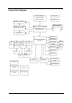
System Block Diagram Intel Pentium-M/ Celeron-M CPU Micro FC-PGA Thermal Sensor Clock Generator CRT & TV-Out Conn. DDR II SODIMM 2 Daughter Card (M26P) PCI-Express x16 Mobile Intel 915PM/ GM and 910GML Express Chipset (Alviso) DDR II SODIMM 1 LVDS Conn. USB Conn. x3 Mobile Intel 82801FB ICH6-M Min i-PCI So cket BroadCOM LAN BCM440 1KFB / BCM578 8M PCMCIA & CardRead er Controller ENE CB7 12 13 94 Con troller TSB34AB21A USB Conn. x1 for BlueTooth Audio Codec Speaker Conn.
Board Layout Top View SW2 SW4 SW5 SW6 SW3 SW1 JP1 2 2 JP5 2 JP4 2 JP7 2 2 KQ: 2 JP42 2 2 JP10 SW3 Power Switch SW1 Lid Swtich JP1 Bluetooth Connector JP5 Touchpad Connector SW2 E-mail Switch JP4 Keyboard Connector SW4 Internet Browser Switch JP42 Speaker Connector SW5 Emanager Switch JP7 PCMCIA Slot SW6 User Programmable Switch JP10 Microphone Connector Chapter 1 5
Bottom View 2 PCN1 JP13 JP12 JP14 2 JP3 2 2 PJP11 JP20 JP17 2 JP16 JP22 2 2 JP21 JP19 2 2 JP23 JP24 2 JP25 2 JP26 JP28 2 2 JP30 2 JP31 JP35 T2 2 Q2 JP29 JP36 2 JP39 2 IR1 2 U42 6 JP41 JP40 JP21 Fan Connector JP24 USB Port PJP11 Battery Connector JP25 USB Port JP20 CPU Socket JP30 IEEE 1394 Port JP16 LVDS Connector JP36 Card Reader Connector JP22 VGA Board Connector IR Infrared Receiver PCN1 AC-IN JP40 Headphone out/line-out Jack (support SPDIF)
A TravelMate tour After knowing your computer features, let us show you around your new TravelMate computer. Front View # Chapter 1 Icon Item Description 1 Display screen Also called LCD (liquid-crystal display), displays computer output. 2 Power button Turns the computer on and off. 3 Launch keys Buttons for launching frequently used programs. See “Launch keys” section for more details. 4 Microphone Internal microphone for sound recording.
Closed Front View # Icon Item Description 1 Speaker-out/line-out/ Headphone jack Connects to audio line-out devices (e.g., speakers, headphones). 2 Mic-in jack Accepts inputs from external microphone. 3 Speakers Left and right speakers deliver stereo audio output. 4 Bluetooth® communication button/ indicator Press to enable/disable Bluetooth function. Lights to indicate the status of Bluetoothcommunications (option only available for TravelMate 3210/3220/3230).
2 S-video/TV-out port Connects to a television or display device with S-video input (TravelMate 3210/3220/ 3230 only). 3 Network jack Connects to an Ethernet 10/100/1000based network. 4 Modem jack Connects to a phone line. 5 Two USB 2.0 ports Connects to USB 2.0 devices (e.g., USB mouse, USB camera). 6 IEEE 1394 port Connects to IEEE 1394 devices (TravelMate 3210/3220/3230 only). 7 PC Card slot Connects to one Type II PC Card.
Right View # 10 Icon Item Description 1 Optical drive Internal optical drive; accepts CDs or DVDs depending on the optical drive type. 2 LED indicator Lights up when the optical drive is active. 3 Optical drive eject button Ejects the opotical drive tray from the drive. 4 Emergency eject hole Ejects the optical drive tray when the computer is turned off. 5 Ventilation slots Enable the computer to stay cool, even after prolonged use.
Rear Panel TravelMate 3210/3230 Rear View # Icon Item Description 1 Battery bay Houses the computer’s battery pack. 2 Power jack Connects to an AC adaptor. 3 Connect to USB 2.0 devices (e.g., USB mouse, USB camera). TravelMate 3220 Rear View # Icon Item 1 Battery bay Houses the computer’s battery pack. 2 Power jack Connects to an AC adaptor. 3 4 Chapter 1 Description Connect to USB 2.0 devices (e.g., USB mouse, USB camera).
Bottom Panel 7 # Item Description 1 Battery bay Houses the computer’s battery pack. 2 Battery lock Locks the battery in place. 3 Cooling fan Helps keep the computer cool. Note: Do not cover or obstruct the opening of the fan. 12 4 Memory compartment Houses the computer’s main memory. 5 Hard disk bay Houses the computer’s hard disk (secured by two screws). 6 Battery release latch Releases the battery for removal. 7 Wireless LAN card compartment Houses the computer’s mini PCI.
Indicators The computer has three easy-to-read status indicators on the upper-left above the keyboard, and four on the front panel. The power, battery and wireless communication status indicators are visible even when the LCD display is closed. Icon Function Description Cap lock Lights when Cap Lock is activated Num lock Lights when Num Lock is activated. Media Activity Indicates when the hard disc or optical drive is active. Bluetooth Indicates the status of Bluetooth communication.
Launch Keys Located at the upper-right, above the keyboard are four buttons. These buttons are called launch keys. The are: mail, Web browser, Acer Empowering key “ “ and one user-programmable button. Press “ “ to ru the Acer eManager. Please see “Acer eManager”. The mail and Web buttons are pre-set to email and Internet programs, but can be reset by users. To set the Web browser, mail and programmable keys, run the Acer Launch Manager.
Touchpad The built-in touchpad is a pointing device that senses movement on its surface. This means the cursor responds as you move your finger across the surface of the touchpad. The central location on the palmrest provides optimum comfort and support. Touchpad Basics The following teaches you how to use the touchpad: T Move your finger across the touchpad (2) to move the cursor. T Press the left (1) and right (4) buttons located beneath the touchpad to perform selection and execution functions.
Function Drag Access context menu Scroll Left Button (1) Right Button (4) Main touchpad (2) Center button (3) Tap twice (at the same speed as doubleclicking a mouse button) then hold finger to the touchpad on the second tap to drag the cursor. Click and hold, then use finger to drag the cursor on the touchpad Click once Click and hold to move up/down/left/right. NOTE: Keep your fingers dry and clean when using the touchpad. Also keep the touchpad dry and clean.
Using the Keyboard The keyboard has full-sized keys and an embedded keypad, separate cursor keys, two Windows keys and twelve function keys. Lock Keys and embedded mumeric keypad The keyboard has three lock keys which you can toggle on and off. Lock Key Description Caps Lock When Caps Lock is on, all alphabetic characters typed are in uppercase. Num lock + When Num Lock is on, the embedded keypad is in numeric mode.
Windows Keys The keyboard has two keys that perform Windows-specific functions. Key Windows key Icon Description Pressed alone, this key has the same effect as clicking on the Windows Start button; it launches the Start menu. It can also be used with other keys to provide a variety of function: + Activates next taskbar button. + Opens the My Computer window + Opens Help and Support. + Opens the Find: All Files dialog box. + Opens the Run dialog box. + Minimizes all windows.
Hot Keys The computer employs hotkeys or key combinations to access most of the computer’s controls like sreen brightness, volume output and the BIOS utility. To activate hot keys, press and hold the key before pressing the other key in the hotkey combination. Hot Key Icon Function Description Fn-F1 Hot key help Displays help on hot keys. Fn-F2 Acer eSetting Launches the Acer eSettings in Acer eManager. Fn-F3 Acer ePowerManagement Launches the Acer ePowerManagement in Acer eManager.
Hot Key 20 Icon Function Description Fn-y Volume down Decreases the speaker volume. Fn-x Brightness up Increases the screen brightness.
Special Key You can locate the Euro symbol and US dollar sign at the upper-center and/or bottom-right of your keyboard. To type: The Euro symbol 1. Open a text editor or word processor. 2. Either directly press the < > symbol at the bottom-right of the keyboard, or hold and then press the<5> symbol at the upper-center of the keyboard. The US dollar sign 1. Open a text editor or word processor. 2.
Hardware Specifications and Configurations Processor Item CPU type Specification TravelMate 3210/TravelMate 3220/TravelMate 3230 Intel® Pentium® M Processor 730/740/750/760/770 (2 MB L2 cache, 1.60/ 1.73/1.86/2/2.13 GHz, 533 MHz FSB) Intel® Pentium® M Processor 725 (2MB L2 cache, 1.6 GHz, 400 MHz FSB) TravelMate 2400 Intel® Pentium® M Processor 725 (2MB L2 cache, 1.6 GHz, 400 MHz FSB) Intel® Celeron® M Processor 350/360/370 (1 MB L2 cache, 1.30/1.40/1.
System Memory Item Specification Supports DIMM package 200-pin soDIMM Memory module combinations You can install memory modules in any combinations as long as they match the above specifications.
IR Interface Item Specification Performance 4Mbit/s Compliant IrDA 1.1 Modem Interface Item Specification Data modem data baud rate (bps) 56K Supports modem protocol V.90/V.92 Modem connector type RJ11 Modem connector location Left side Bluetooth Interface Item Specification Chipset built-in Mobile Intel 82801FB (ICH6-M) Data throughput 723 bps (full speed data rate) Protocol Bluetooth 1.1 (Upgradeable to Bluetooth 1.2 when SIG specification is ratified). ® Interface USB 1.
Hard Disk Drive Interface Item Specification Spindle speed (RPM) 4200/4200 RPM 4200/4200 RPM 4200/4200 RPM 4200/4200 RPM 8192KB 8192KB 8192KB Performance Specifications Buffer size 2MB/8192KB Interface ATA/ATAPI-6; ATA-6 ATA/ATAPI-6; ATA-6 ATA/ATA-6; ATA-6 ATA/ATA-6; ATA-6 Max. media transfer rate (disk-buffer, Mbytes/s) 372 350 350 373 Data transfer rate (host~buffer, Mbytes/s) 100 MB/Sec. Ultra DMA mode-5 100 MB/Sec. Ultra DMA mode-5 100 MB/Sec. Ultra DMA mode-5 100 MB/Sec.
DVD-Dual Interface Item Transfer rate (KB/sec) Specification Sustained: Max 3.6Mbytes/sec Sustained: Max 10.8Mbytes/sec Buffer Memory 2MBytes Interface Enhanced IDE(ATAPI) compatible Applicable disc format for LiteOn SOSW-833S Read: DVD: DVD single/dual layer (PTP, OTP), DVD-R (3.9G/4.
Audio Interface Item Audio Controller Specification ALC250 Audio onboard or optional Built-in Mono or Stereo Stereo Resolution 18 bit stereo digital to analog converter 18 bit stereo analog to digital converter Compatibility AC97 Mixed sound source Line-in, CD Voice channel 8/16-bit, mono/stereo Sampling rate 44,1 KHz (48K byte for AC97 interface) Internal microphone Yes Internal speaker / Quantity Yes/2 Video Interface Item Specification Chipset ATI Mobility RADEON® X700 (for discret
PCMCIA Port Item Specification PCMCIA controller ENE CB712 Supports card type Type-II Number of slots One type-II Access location Left panel Supports ZV (Zoomed Video) port No ZV support Supports 32 bit CardBus Yes System Board Major Chips Item Core logic Controller ® Intel 915GM/PM (for TravelMate 3210/3220/3230)/Intel® 910GML (for TravelMate 2400)+Intel® ICH6-M (Mobile Intel 82801FB) VGA ATI Mobility RADEON® X700 (for discrete models) LAN BroadCom BCM4401(10/100M for TravelMate 2400);
Battery Item Specification Vendor & model name BATTERY LI-ION 6 CELLS-SANYO 2000mAH UR18650F BATTERY LI-ION 6 CELLS-SONY 2000mAH US18650G4 BATTERY LI-ION 6 CELLS-SANYO 2400mAH UR18650F BATTERY LI-ION 6 CELLS-SONY 2400mAH US18650G7 BATTERY LI-ION 9 CELLS-SANYO 2400mAH UR18650F Battery Type Li-ion Pack capacity 4800mAh 6cell and 7200mAh 9cell for TravelMate 3210 4000mAh 6cell for TravelMate 2400 Number of battery cell 53.3W 6cell and 79.9W 9cell for TravelMate 3210 44.
LCD 14.
Chapter 1 31
32 Chapter 1
Chapter 2 System Utilities BIOS Setup Utility The BIOS Setup Utility is a hardware configuration program built into your computer’s BIOS (Basic Input/ Output System). Your computer is already properly configured and optimized, and you do not need to run this utility. However, if you encounter configuration problems, you may need to run Setup. Please also refer to Chapter 4 Troubleshooting when problem arises.
Navigating the BIOS Utility There are six menu options: Info., Main, System Devices, Security, Boot, and Exit. Follow these instructions: T To choose a menu, use the cursor left/right keys (zx). T To choose a parameter, use the cursor up/down keys ( wy). T To change the value of a parameter, press por q. T A plus sign (+) indicates the item has sub-items. Press e to expand this item. T Press ^ while you are in any of the menu options to go to the Exit menu.
Main Insyde Software SCU Main Sep 20, 2005 11:40:09 AM Advanced Security Boot ----Devices--------------------------------------------------Product Name -----System------------------------CPU = Intel® Pentium ® M = TravelMate 3210 Light CPU speed = 1.73 GHz Manufacture Name = Acer BIOS Version = V1.
Parameter Description CPU speed L2 Cache This field displays CPU L2 cache size. It varies in CPU type. System Memory This field reports the memory size of system base memory. The size is fixed to 640 KB. Extended Memory This field reports the memory size of the extended memory in the system.
The table below describes the parameters in this screen. Settings in boldface are the default and suggested parameter settings. Parameter Description Date and Time The hours are displayed with 12 hour format. The values setin these two fields take effect immediately. Quiet Boot Determines if the system will display customer logo and summary screen or not. Format/Option Option: Enabled or Disabled Enable: Customer logo is displayed, and summary screen is disabled.
Advanced The Advanced menu screen contains parameters involving your hardware devices. It also provides advanced settings of the system. Insyde Software SCU Main Sep 30, 2005 Advanced Security 11:40:09 Boot AM Exit --------------------------Infrared Port(FIR)----------------------- Infrared Port (FIR) Max.
Security The Security screen contains parameters that help safeguard and protect your computer from unauthorized use. Insyde Software SCU Main Sep 30, 2005 Advanced Security 11:40:09 Boot AM Exit Set User Password Set Supervisor Password _ Lock HardDisk Drive --------Set Supervisor password---------------Enter old Supervisor password: .......... Enter new Supervisor Password: . . . . . . . . . .. Verify new Supervisor Password: .......... [ ] Boot System OK Cancel Enter new password.
Boot This menu allows the user to decide the order of boot devices to load the operating system. Bootable devices includes the distette drive in module bay, the onboard hard disk drive and the CD-ROM in module bay. Insyde Software SCU Main Advanced Se[ 30, 2005 11:40:09 Security Boot Boot Device ----- Boot Device AM Exit ` ---- Hard Drive CD-ROM/DVD Drive Floppy Device Network Boot Press key to select a control. button or key accept entries.
Exit The Exit screen contains parameters that help safeguard and protect your computer from unauthorized use. Insyde Software SCU Main Sep 30, 2005 11:40:09 Advanced Security Boot Exit Exit Saving Changes --------------Exit Saving Changes-----------------Press to save the current Setup parameters to CMOS RAM. Exit Discarding Changes Load Setup Defaults Discard Changes The system will reboot!!! OK for block select. Cancel for item select.
BIOS Flash Utility The BIOS flash memory update is required for the following conditions: T New versions of system programs T New features or options T Restore a BIOS when it becomes corrupted. Use the Phlash utility to update the system BIOS flash ROM. NOTE: If you do not have a crisis recovery diskette at hand, then you should create a Crisis Recovery Diskette before you use the Phlash utility. NOTE: Do not install memory-related drivers (XMS, EMS, DPMI) when you use the Phlash.
Remove BIOS Password Please find J3 jumper on the main board. Then short the jumper to remove BIOS supervisor password. J3 locates under the memory module. Please see the image below.
Chapter 3 Machine Disassembly and Replacement This chapter contains step-by-step procedures on how to disassemble the notebook computer for maintenance and troubleshooting. To disassemble the computer, you need the following tools: T Wrist grounding strap and conductive mat for preventing electrostatic discharge T Small Philips screw driver T Philips screwdriver T Plastic flat head screw driver Tweezers NOTE: The screws for the different components vary in size.
General Information Before You Begin Before proceeding with the disassembly procedure, make sure that you do the following: 44 1. Turn off the power to the system and all peripherals. 2. Unplug the AC adapter and all power and signal cables from the system. 3. Remove the battery pack.
Disassembly Procedure Flowchart The flowchart on the succeeding page gives you a graphic representation on the entire disassembly sequence and instructs you on the components that need to be removed during servicing. For example, if you want to remove the system board, you must first remove the keyboard, then disassemble the inside assembly frame in that order.
LCD Module 4 screw caps *4 LCD Bezel *2 *2 LCD Inverter LCD Panel LCD Assembly *8 LCD LCD Wire Cable LCD Brackets Screw List Item A 46 Description SCW HEX NYL I#R-40/O#4-40 L5.5 B SCREW MACH WAFER M2*L4 NI C CPU SCREW M2.5*6.5 (2.7KG) D CPU SCREW M2.5*6.5 (4.5KG) E SCRW WH MS+CBZ M2.5+L4 BLACK F SCREW M2.5-6 G SCREW M2*3 NYLON 1JMCPC-420325 H SCREW M2.5X6 I SCREW M2-3 J SCRW M2.5*L3(NON NYLOK) K SCREW M2.5-5 L SCREW M3x4(86.9A524.
Removing the Battery Pack 1. Unlock the battery lock. 2. Slide the battery latch then remove the battery.
Removing the Wireless LAN Card/the HDD Module/the Memory/the CPU/ the ODD Module and the LCD Module Removing the Wireless LAN Card and the HDD Module 1. Remove the two screws fastening the PCI door. 2. Detach the PCI door. 3. Disconnect the wireless antennae. 4. Pop out the wireless LAN card then remove it. 5. Remove the two screws fastening the HDD cover. 6. Remove HDD cover carefully. 7. Pull the HDD module backwards to disconnect the HDD module then remove it from the main unit.
4. Remove the two screws fastening the thermal door. 5. Detach the thermal door from the main unit. 6. Remove the four screws holding the thermal module. (Follow the order indicated by the numbers: 4, 3, 2 then1. Please reverse the order when you assemble the system). 7. Disconnect the fan cablle as shown. 8. Take out the thermal module from the main unit carefully. 9. Use a flat headed screwdriver to release the CPU lock. 10. Then remove the CPU from the CPU socket carefully.
3. Open the LCD module as shown and detach the middle cover carefully. 4. Remove the two screws fastening the keyboard. 5. Turn over the keyboard as shown. 6. Disconnect the keyboard cable then remove the keyboard. 7. Tear off the mylard festening the wireless antenna set. 8. Pull out the wireless antenna from the main unit carefully. 9. Disconnect the LCD cable from the main board. 10. Remove two screws holding the LCD module. 11.
Chapter 3 51
Disassembling the Main Unit Separate the Main Unit Into the Upper and the Lower Case Assembly 1. To separate the upper and the lower case assembly, remove six screws as shown. 2. Turn over the main unit, remove 9 screws on the other side. 3. Separate the main unit into the upper case assembly and the lower case assembly. Disassembling the Upper Case Assembly 52 1. Disconnect the touchpad FFC from the main board. 2. Disconnect the bluetooth cable. 3.
10. Detach the touchpad support from the upper case carefully. 11. Detach the touchpad from the upper case. 12. Disconnect the FFC from the touchpad. Disassembling the Lower Case Assembly 1. Remove four screws fastening the main board to the lower case. 2. Turn over the lower case assembly, then remove one screw on the other side as shown. 3. Disconnect the speaker cable. 4. Detach the main board assembly from the lower case carefully. 5. Remove the three screws fastening the VGA board. 6.
8. Detach the VGA thermal from the VGA board. 9. Disconnect the modem cable from the main board. 10. Remove the two screws fastening the modem board as shwon. 11. Disconnect the modem board from the main board. 12. Disconnect the modem cable from the modem board. 13. Remove the two screws holding the speaker set to the lower case. 14. Take out the speaker set from the lower case. This completes the main unit disassembly.
Disassembling the LCD Module 1. Remove the four screw caps as shown. 2. Remove the four screws holding the LCD bezel. 3. Then detach the LCD bezel from the LCD module. 4. Remove the screw fastening the LCD inverter. 5. Disconnect the LCD cable and disconnect the inverter cable, then remove the inverter. 6. Remove the two screws fastening the LCD assembly to the LCD panel. 7. Take out the LCD assembly from the LCD panel. 8. Remove the four screws fastening the LCD left bracket then remove it.
Disassembling the External Modules Disassembling the HDD Module 1. Remove the two screws holding the HDD bracket on one side. 2. Remove another two screws holding the HDD bracket on the other side. 3. Then take the hard disc drive out of the HDD bracket. Disassembling the ODD Module 56 1. Remove the two screws fastening the ODD bracket. 2. Remove the ODD bracket from the optical disc drive module.
Chapter 4 Troubleshooting Use the following procedure as a guide for computer problems. NOTE: The diagnostic tests are intended to test this model. Non-Acer products, prototype cards, or modified options can give false errors and invalid system responses. 1. Duplicate symptom and obtain the failing symptoms in as much detail as possible. 2. Distinguish symptom. Verify the symptoms by attempting to re-create the failure by running the diagnostic test or by repeating the same operation. 3.
System Check Procedures External Diskette Drive Check If an error occurs with the internal diskette drive, reconnect the diskette connector on the system board. If the error still remains: 1. Reconnect the external diskette drive/DVD-ROM module. 2. Replace the external diskette drive/CD-ROM module. 3. Replace the main board. External CD-ROM Drive Check Do the following to isolate the problem to a controller, drive, or CD-ROM. Make sure that the CD-ROM does not have any label attached to it.
Power System Check To verify the symptom of the problem, power on the computer using each of the following power sources: 1. Remove the battery pack. 2. Connect the power adapter and check that power is supplied. 3. Disconnect the power adapter and install the charged battery pack; then check that power is supplied by the battery pack.
Check the Battery Pack To check the battery pack, do the following: From Software: 1. Check out the Power Management in control Panel 2. In Power Meter, confirm that if the parameters shown in the screen for Current Power Source and Total Battery Power Remaining are correct. 3. Repeat the steps 1 and 2, for both battery and adapter. 4. This helps you identify first the problem is on recharging or discharging. From Hardware: 1. Power off the computer. 2.
Insyde MobilePro BIOS POST Beep Code and POST Messages The POST error message index lists the error message and their possible causes. The most likely cause is listed first. NOTE: Perform the FRU replacement or actions in the sequence shown in FRU/Action column, if the FRU replacement does not solve the problem, put the original part back in the computer. Do not replace a non-defective FRU. This index can also help you determine the next possible FRU to be replaced when servicing a computer.
Beep Code 62 Message Description N/A “NO INTERRUPTS FROM TIMER 0” Timer 0 of the clock timer controller does not generate system interrupts correctly. N/A “UNEXPECTED AMOUNT OF MEMORY - RUN SCU” The system memory size does not match with the CMOS record. N/A “CLOCK NOT TICKING CORRECTLY” The system clock does not working correctly. N/A “TIME/DATA CORRUPT - RUN SCU” The time/date information in CMOS is invalid. N/A “MACHINE IS LOCKED - TURN KEY” The keyboard operation is locked.
Insyde MobilePro BIOS POST Codes POST Code Macro Name Description Boot Loader--BLOAD.ASM 00 DIAG_SYSTEM_INIT Boot started, check motherboard power is stable.
POST Code Macro Name Description 23 DEBUG_POST_TEST_BATT_CMOS_ Test Battery Fail & check CMOS X-SUM SUM 24 DEBUG_HWIO_TEST_DMA_CTLRS Use DMA to copy data for Test the DMA controllers 25 DEBUG_HWIO_INIT_8237 Initialize 8237A Controller 26 DEBUG_POST_INIT_VECS Install and Initialize interrupt Vectors 27 DEBUG_RAM_QUICK_SIZE Enter memory protect mode, use change RAM bank to do RAM Quick Sizing 28 DEBUG_RAM_PROT_ENTRY_1 Memory protected mode entered safely 29 DEBUG_RAM_SIZE_DONE Test the b
POST Code Macro Name Description 44 DEBUG_OEM_INIT_POWER_MAN Check special device initial power management function 45 DEBUG_KEYB_SET_LEDS_2 Clear keyboard buffer and Update NUMLOCK status 46 DEBUG_HWIO_FIND_80X87 Test For Coprocessor Installed, and enable coprocessor interrupt 47 DEBUG_OEM_LAST_MINUTE_INIT Run OEM functions before boot, and enable L1,L2 cache 48 DEBUG_MISC_LAUNCH_INT19 Post code will finish, ready to run int19 and load OS 49 DEBUG_BEGIN_BOOT_CODE Into Int19, to boot fro
POST Code Macro Name Description E6 DEBUG_RET_PCI_2 PCI device config finish E7 DEBUG_BRIDGE_HUNT Search for PCI bridge controllor device E8 DEBUG_PCI_IDE_FIND Search IDE controllors on the PCI bus, and config the IDE controllors E9 DEBUG_CB_CONFIG start of cardbus config A1 DEBUG_PNP_ENABLE_VERIFY_RT DATA Enable and Verify R/W Status for PNP BIOS Runtime Data Area A2 DEBUG_PNP_GET_VERIFY_NVRAM Get and Verify R/W Status for PNP BIOS NVRAM data area A3 DEBUG_PNP_SYSTEM_NODES Resolve Sys
Index of Symptom-to-FRU Error Message LCD-Related Symptoms Symptom / Error LCD backlight doesn't work Action in Sequence First, plug a monitor to CRT port. Next, enter BIOS utility to running “Load Default Settings” then reboot the system. Reconnect the LCD connectors. Keyboard (if the brightness function key doesn't work). LCD cable LCD inverter LCD Main board LCD is too dark LCD brightness cannot be adjusted Enter BIOS Utility to execute “Load Setup Default Settings”, then reboot system.
Power-Related Symptoms Symptom / Error Battery can’t be charged or discharged Action in Sequence See “Check the Battery Pack” on page 60. Battery pack Main board System hang during POST ODD/HDD/FDD/RAM module Main board PCMCIA-Related Symptoms Symptom / Error System cannot detect the PC Card (PCMCIA) Action in Sequence PCMCIA slot assembly Main board PCMCIA slot pin is damaged.
Power Management-Related Symptoms Symptom / Error The system doesn't resume from hibernation/ standby mode. Action in Sequence Connect AC adapter then check if the system resumes from Standby/Hibernation mode. Check if the battery is low. Hard disk drive Main board The system doesn't resume from standby mode after opening the lid of the portable computer. LCD cover switch Battery fuel gauge in Windows doesn’t go higher than 90%.
Modem/LAN-Related Symptoms Symptom / Error Internal modem does not work correctly. Action in Sequence Phone cable Driver Reconnect the Internal modem cable to the main board tightly. Main board Internal LAN does not work correctly Lan cable Driver Main board NOTE: If you cannot find a symptom or an error in this list and the problem remains, see “Undetermined Problems” on page 72.
Intermittent Problems Intermittent system hang problems can be caused by a variety of reasons that have nothing to do with a hardware defect, such as: cosmic radiation, electrostatic discharge, or software errors. FRU replacement should be considered only when a recurring problem exists. When analyzing an intermittent problem, do the following: 1. Run the diagnostic test for the system board in loop mode at least 10 times. 2. If no error is detected, do not replace any FRU. 3.
Undetermined Problems The diagnostic problems does not identify which adapter or device failed, which installed devices are incorrect, whether a short circuit is suspected, or whether the system is inoperative. Follow these procedures to isolate the failing FRU (do not isolate non-defective FRU). NOTE: Verify that all attached devices are supported by the computer. NOTE: Verify that the power supply being used at the time of the failure is operating correctly. (See “Power System Check” on page 59): 72 1.
Chapter 5 Jumper and Connector Locations Top View SW2 SW4 SW5 SW6 SW3 SW1 JP1 2 2 JP5 2 JP4 2 JP7 2 2 KQ: 2 JP42 2 2 JP10 SW3 Power Switch SW1 Lid Swtich JP1 Bluetooth Connector JP5 Touchpad Connector SW2 E-mail Switch JP4 Keyboard Connector SW4 Internet Browser Switch JP42 Speaker Connector SW5 Emanager Switch JP7 PCMCIA Slot SW6 User Programmable Switch JP10 Microphone Connector Chapter 5 73
Bottom View 2 PCN1 JP13 JP12 JP14 2 JP3 2 2 PJP11 JP20 JP17 2 JP16 JP22 2 2 JP21 JP19 2 2 JP23 JP24 2 JP25 2 JP26 JP28 2 2 JP30 2 JP31 JP35 T2 2 Q2 JP29 JP36 2 JP39 2 IR1 2 U42 74 JP41 JP21 Fan Connector JP24 USB Port PJP11 Battery Connector JP25 USB Port JP40 JP20 CPU Socket JP30 IEEE 1394 Port JP16 LVDS Connector JP36 Card Reader Connector JP22 VGA Board Connector IR Infrared Receiver PCN1 AC-IN JP40 Headphone out/line-out Jack (support SPDIF)
Chapter 6 FRU (Field Replaceable Unit) List This chapter gives you the FRU (Field Replaceable Unit) listing in global configurations of TravelMate 2400/ 3210/32203230 series products. Refer to this chapter whenever ordering for parts to repair or for RMA (Return Merchandise Authorization). Please note that WHEN ORDERING FRU PARTS, you should check the most up-to-date information available on your regional web or channel.
Exploded Diagram The System 011 012 013 76 Chapter 6
Upper Case Assembly Chapter 6 77
Lower Case Assembly 78 Chapter 6
LCD Module Chapter 6 79
HDD Module ODD Module NOTE: Below is TravelMate 2400/3210/3220 FRU List. The columns highlighted in blue indicate the differential parts for TravelMate 3220.
TravelMate 2400/3210/3220/3230 FRU List Picture No. Part Name and Description Part Number Adapter NS (Not Show) ADAPTER 3 PIN 65W DELTA SADP-65KB BEF 19V 3PIN AP.06501.006 ADAPTER 3 PIN 65W LITEON PA-1650-02CO 65W 3 PIN AP.06503.007 ADAPTER 3 PIN 65W HIPRO HPOK066B13CP 3P 65W AP.0650A.004 BATTERY LI-ION 6 CELLS-SANYO 2000mAH UR18650F BT.00603.001 BATTERY LI-ION 6 CELLS-SONY 2000mAH US18650G4 BT.00604.004 BATTERY LI-ION 6 CELLS-SANYO 2400mAH UR18650F BT.00604.
TravelMate 2400/3210/3220/3230 FRU List Picture No. Part Name and Description Part Number The System013 VGA BOARD M26P 64MB 55.A70V5.002 Upper Case Assembly004 FFC CABLE - T/P TO T/P BOARD 50.A70V5.001 NS BLUETOOTH CABLE 50.A70V5.002 NS MODEM CABLE 50.A70V5.003 NS POWER CORD-AUS 27.A70V5.001 NS POWER CORD-CHINA 27.A70V5.002 NS POWER CORD-DENMARK 27.A70V5.003 NS POWER CORD-EC 27.A70V5.004 NS POWER CORD-INDIA 27.A70V5.005 NS POWER CORD-ISREL 27.A70V5.
TravelMate 2400/3210/3220/3230 FRU List Picture No. Part Name and Description Part Number The System254; Upper Case Assembly001 UPPER CASE-TM 60.TAAV5.001 NS UPPER CASE FOR DUCKING(TravelMate 3220) 60.TAMV5.001 The System002 LOWER CASE- UMA 60.A70V5.002 NS LOWER CASE- NON UMA 60.A70V5.003 NS LOWER CASE FOR DUCKING(TravelMate 3220) 60.TAMV5.002 Upper Case Assembly002 4 - WAY BUTTON 42.A70V5.002 Upper Case Assembly003 TP SUPPORT 33.A70V5.001 Lower Case Assembly003 DIMM COVER 42.
TravelMate 2400/3210/3220/3230 FRU List Picture No. Part Name and Description Part Number NS CELERON M 350 (1.3G 1M) C0 KC.NC001.350 NS CELERON M 360 (1.4G 1M) C0 KC.NC001.360 NS CELERON M 370 (1.5G 1M) C0 KC.NC001.370 NS INTEL PENTIUM M DOTHAN 1.6GHZ 2M UFCBGA SL7EG B-1 STEPPING KC.N0001.725 NS INTEL PENTIUM M 1.6G 2M 533FSB uFCPGA2 SL86G C-1 STEPPING KC.N0001.730 NS INTEL PENTIUM M 1.73G 2M 533FSB uFCPGA2 SL7SA C-1 STEPPING KC.N0001.740 NS INTEL PENTIUM M 1.
TravelMate 2400/3210/3220/3230 FRU List Picture No. Part Name and Description Part Number ODD Module002 DVD DUAL BEZEL - TRAY IN 42.A70V5.008 ODD Module003 ODD BRACKET 33.A70V5.002 ODD Module DVD DUAL MODULE 8X HLDS GWA-4082N (DL) 6M.A70V5.007 ODD Module001 DVD DUAL 8X DRIVE HLDS GWA-4082N (DL) KU.0080D.016 ODD Module002 DVD DUAL BEZEL - TRAY IN 42.A70V5.008 ODD Module003 ODD BRACKET 33.A70V5.002 ODD Module SUPER MULTI MODULE 8X PANASONIC UJ840BAA (DL) 6M.A70V5.
TravelMate 2400/3210/3220/3230 FRU List Picture No. Part Name and Description Part Number HDD Module001 HDD BRACKET 33.A70V5.003 Lower Case Assembly008 HDD DOOR 42.A70V5.011 The System011 KEYBOARD DARFON CHINESE KB.T5902.001 KEYBOARD DARFON US INTERNATIONAL KB.T5902.002 KEYBOARD DARFON THAI KB.T5902.003 KEYBOARD DARFON GERMAN KB.T5902.004 KEYBOARD DARFON UK KB.T5902.005 KEYBOARD DARFON ITALIAN KB.T5902.006 KEYBOARD DARFON FRENCH KB.T5902.007 KEYBOARD DARFON SWISS/G KB.T5902.
TravelMate 2400/3210/3220/3230 FRU List Picture Chapter 6 No. Part Name and Description Part Number LCD Module007 LCD INVERTER 19.A70V5.001 LCD Module006 LCD WIRE CABLE 50.A70V5.005 LCD Module004 LCD PANEL WITH LOGO W/ANTENNA - TM 60.TAAV5.002 LCD Module005 LCD BEZEL 60.A70V5.006 LCD Module002, 003 LCD BRACKET SET 6K.A70V5.001 LCD Module ASSY LCD MODULE 14.1 WXGA NON GLARE CMO (N141l 1-L03) W/ANT-TM 6M.TAAV5.004 LCD Module001 LCD 14.1 WXGA NON GLARE CMO (N141l 1L02) LK.1410D.
TravelMate 2400/3210/3220/3230 FRU List Picture 88 No. Part Name and Description Part Number LCD Module006 LCD WIRE CABLE 50.A70V5.005 LCD Module004 LCD PANEL WITH LOGO W/ANTENNA - TM 60.TAAV5.002 LCD Module005 LCD BEZEL 60.A70V5.006 LCD Module002, 003 LCD BRACKET SET 6K.A70V5.001 LCD Module ASSY LCD MODULE 14 .1 WXGA NON GLARE QDI (N141V2 QD14TL01 REV 01) W/ O ANT - TM 6M.TAAV5.007 LCD Module001 LCD 14 .1 WXGA NON GLARE QDI N141V2 QD14TL01 REV 01 LK.14109.
TravelMate 2400/3210/3220/3230 FRU List Picture Chapter 6 No. Part Name and Description Part Number LCD Module004 LCD PANEL WITH LOGO W/O ANTENNA TM 60.TAAV5.003 LCD Module005 LCD BEZEL 60.A70V5.006 LCD Module002, 003 LCD BRACKET SET 6K.A70V5.001 LCD Module ASSY LCD MODULE 14.1 WXGA NON GLARE CMO (N141l 1-L03) W/O ANT-TM 6M.TAAV5.008 LCD Module001 LCD 14.1 WXGA NON GLARE CMO (N141l 1L02) LK.1410D.004 LCD Module007 LCD INVERTER 19.A70V5.001 LCD Module006 LCD WIRE CABLE 50.A70V5.
TravelMate 2400/3210/3220/3230 FRU List Picture No. Part Name and Description Part Number LCD Module005 LCD BEZEL 60.A70V5.006 LCD Module002, 003 LCD BRACKET SET 6K.A70V5.001 The System251 MAINBOARD 915PM FOR VGA GLAN W/ READER PCMCIA SLOT W/O CPU MEMORY LB.TAA02.002 MAINBOARD 915GM UMA GLAN W/ READER PCMCIA SLOT W/O CPU MEMORY LB.TAA02.001 MAINBOARD 910GML UMA GLAN W/ PCMCIA SLOT W/O READER CPU MEMORY LB.TA902.
TravelMate 2400/3210/3220/3230 FRU List Picture No. Part Name and Description Part Number Upper Case Assembly005 TOUCHPAD 56.A70V5.001 NS SPEAKER SET (R&L) 23.A70V5.002 NS LCD RUBBER PAD 47.A70V5.001 NS LCD SCREW PAD 47.A70V5.002 NS LCD RUBBER 47.A70V5.003 NS NAME PLATE - TM3210 47.TAAV5.001 NS NAME PLATE - TM3220 40.TAMV5.001 NS NAME PLATE - TM2400 47.TA9V5.001 NS RUBBER FOOT - ONE PIN 47.A70V5.004 NS RUBBER FOOT - TWO PINS 47.A70V5.005 SCREW NS SCREW M2*3(NL) 86.A70V5.
92 Chapter 6
Chapter 6 93