
User's Manual

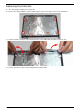
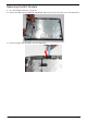
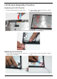
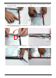
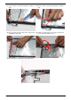
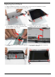
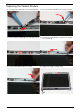
Table Of Contents
- System Specifications
- System Utilities
- Machine Disassembly and Replacement
- Disassembly Requirements
- General Information
- External Module Disassembly Process
- Main Unit Disassembly Process
- Main Unit Disassembly Flowchart
- Removing the Hinge Covers
- Removing the Switch Cover
- Removing the Keyboard
- Removing the Speaker Module
- Removing the LCD Module
- Removing the Upper Cover
- Removing the Finger Print Reader
- Removing the TouchPad Bracket
- Removing the RTC Battery
- Removing the Bluetooth Module
- Removing the USB Board
- Removing the Modem Module
- Removing the Mainboard
- Removing the RJ-11 Port
- Removing the Thermal Module
- Removing the CPU
- LCD Module Disassembly Process
- LCD Module Reassembly Procedure
- Main Module Reassembly Procedure
- Replacing the CPU
- Replacing the Thermal Module
- Replacing the RJ-11 Port
- Replacing the Mainboard
- Removing the RTC Battery
- Replacing the USB Board
- Replacing the Bluetooth Board
- Replacing the Modem Module
- Replacing the TouchPad Bracket
- Replacing the Finger Print Reader
- Replacing the Upper Cover
- Replacing the LCD Module
- Replacing the Speaker Module
- Replacing the Keyboard
- Replacing the Switch Cover
- Replacing the Hinge Covers
- External Module Reassembly Process
- Troubleshooting
- Common Problems
- Power On Issue
- No Display Issue
- Random Loss of BIOS Settings
- LCD Failure
- Built-In Keyboard Failure
- Touchpad Failure
- Internal Speaker Failure
- Internal Microphone Failure
- HDD Not Operating Correctly
- ODD Failure
- USB Failure (Rightside)
- Modem Function Failure
- Wireless Function Failure
- Bluetooth Function Failure
- EasyTouch Button Failure
- Media Board Failure
- Fingerprint Reader Failure
- Thermal Unit Failure
- External Mouse Failure
- Other Failures
- Intermittent Problems
- Undetermined Problems
- POST Codes Tables
- Common Problems
- Jumper and Connector Locations
- FRU (Field Replaceable Unit) List
- Model Definition and Configuration
- Test Compatible Components
- Online Support Information
- Index
98 Chapter 3
Replacing the LCD Panel
1. Align the LCD brackets with the six screw holes (three on each side) on the LCD Panel as shown.
2.
Replace the six securing screws in numeric order, from 1 to 3.
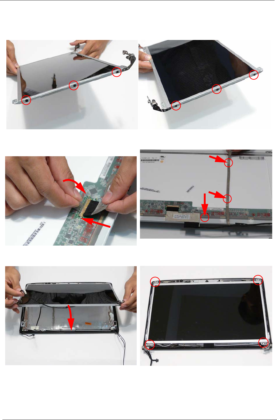
3. Turn the panel over. Insert the LCD Panel cable
into the LCD Panel as shown (1). Secure the cable
by replacing the securing strip (2).
4. Run the LCD cable as shown and press down
along the length of the cable to secure it in place.
5. Insert the LCD panel into the casing back edge first
as shown.
6. Ensure that the four locating pins are properly
seated before continuing.
2
3
1
2
1
3
2
1