
Datasheet


10
Monitor software enabling multiple, independent software environments inside a single
platform. Further details on Intel Virtualization Technology can be found at
http://developer.intel.com/technology/platform-technology/virtualization/index.htm.
The Dual-Core Intel® Xeon® Processor 5200 Series is intended for high performance
server and workstation systems. The Dual-Core Intel® Xeon® Processor 5200 Series
supports a Dual Independent Bus (DIB) architecture with one processor on each bus,
up to two processor sockets in a system. The DIB architecture provides improved
performance by allowing increased FSB speeds and bandwidth. The Dual-Core Intel®
Xeon® Processor 5200 Series will be packaged in an FC-LGA Land Grid Array package
with 771 lands for improved power delivery. It utilizes a surface mount LGA771 socket
that supports Direct Socket Loading (DSL).
The Dual-Core Intel® Xeon® Processor 5200 Series-based platforms implement
independent core voltage (V
CC
) power planes for each processor. FSB termination
voltage (V
TT
) is shared and must connect to all FSB agents. The processor core voltage
utilizes power delivery guidelines specified by VRM/EVRD 11.0 and its associated load
line (see Voltage Regulator Module (VRM) and Enterprise Voltage Regulator-Down
(EVRD) 11.0 Design Guidelines for further details). VRM/EVRD 11.0 will support the
power requirements of all frequencies of the Dual-Core Intel® Xeon® Processor 5200
Series including Flexible Motherboard Guidelines (FMB) (see Section 2.13.1). Refer to
the appropriate platform design guidelines for implementation details.
The Dual-Core Intel® Xeon® Processor 5200 Series supports either 1333 MHz, or
1600 MHz Front Side Bus operations. The FSB utilizes a split-transaction, deferred reply
protocol and Source-Synchronous Transfer (SST) of address and data to improve
performance. The processor transfers data four times per bus clock (4X data transfer
rate, as in AGP 4X). Along with the 4X data bus, the address bus can deliver addresses
two times per bus clock and is referred to as a ‘double-clocked’ or a 2X address bus. In
addition, the Request Phase completes in one clock cycle. The FSB is also used to
deliver interrupts.
Signals on the FSB use Assisted Gunning Transceiver Logic (AGTL+) level voltages.
Section 2.1 contains the electrical specifications of the FSB while implementation
details are fully described in the appropriate platform design guidelines (refer to
Section 1.3).
1.1 Terminology
A ‘#’ symbol after a signal name refers to an active low signal, indicating a signal is in
the asserted state when driven to a low level. For example, when RESET# is low, a
reset has been requested. Conversely, when NMI is high, a nonmaskable interrupt has
occurred. In the case of signals where the name does not imply an active state but
describes part of a binary sequence (such as address or data), the ‘#’ symbol implies
that the signal is inverted. For example, D[3:0] = ‘HLHL’ refers to a hex ‘A’, and
D[3:0]# = ‘LHLH’ also refers to a hex ‘A’ (H= High logic level, L= Low logic level).
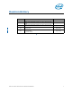
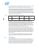
Table 1-1. Dual-Core Intel® Xeon® Processor 5200 Series
# of
Processor
Cores
L1 Cache
L2 Advanced
Cache
Front Side Bus
Frequency
Package
2
32 KB instruction per core
32 KB data per core
6 MB shared 1600 MHz
1333 MHz
1066 MHz
FC-LGA
771 Lands