Acer Acer –LCD-X193HQ Service Manual LCD Monitor Acer X193HQ -0-
1 Table of Contents Important Safety Notice .....................................................................................01 01 Product Specification ......................................................................................03 02 Flat Panel Specification ..................................................................................18 03 Exploded Diagram ...........................................................................................37 04 Troubleshooting ...............
Acer Acer –LCD-X193HQ Important Safety Notice 1. Safety precautions This monitor is manufactured and tested on a ground principle that a user’s safety comes first. However, improper used or installation may cause damage to the monitor as well as to the user. Warning: This monitor should be operated only at the correct power sources indicated on the label on the rear of the monitor. If you’re unsure of the power supply in you residence, consult your local dealer or Power Company.
Acer Acer –LCD-X193HQ 01 Product Specification 1. General: Acer X193HQ is designed with LVDS interface and dual (analog and digital signal) input, it featured with embedded universal AC power supplies and audio input. It’s a green product and meets all ROHS standard. The power button and display control buttons are on the front of the monitor. The monitors shall automatically to display lower resolution video modes into 1366x768 full screen display. The image can be adjusted through OSD control. 1.
Acer Acer –LCD-X193HQ Temperature range -20°C to 60°C Relative humidity 5% to 80% Altitude 0 to 12191M (40000 ft) 2.2 Safety, EMC, Ergonomics and Compatibility Requirements Items Description Safety EMC Ergonomics UL/cUL CB TUV/GS CCC BSMI ● ● ● ● ● FCC-B CE/EMC CCC VCCI C-Tick BSMI ● ● ● ● ● ● TCO99 TCO03 Nemko/Erg o ● ● Compatibility Other Windows 95/98/Me Windows 2000 Windows XP Vista ● ● ● ● Energy Star Power Management ● 2.
Acer Acer –LCD-X193HQ DC Output Voltage and Current Power consumption +5.2V audio output VCC14.2V(13.5~16.3V); VCC5.2V(4.95~5.45V); Audio VCC5.2V(4.95~5.45V) with Audio <200mv 0.8A(typ.),1.0A(max) 0.8A(typ.),1.0A(max) 0.5A(typ.),0.6A(max) ≤25W Protection See Table-1 Power management See Table-2 Note2. Before each test, the buck capacitor need to be discharged. Before each test, it must be 10 minutes at least after the latest test. Note4. ested by DC loading side parallel with a 47uF/EC and 0.
Acer Acer –LCD-X193HQ The test to verify specifications in this section shall be performed under the following standard conditions unless otherwise noted. Temperature Test pattern Video Resolution Video input level Warm-up time : 25 ± 5°C : white : 1366 x 768 : 700 mV ± 2% : 30 minutes LCD Module BL ≥250 cd/m M185XW01-V0 2 Set brightness control and also contrast control at maximum, to measure the screen center, the light output shall ≥ BL cd/m2 (as panel spec) 3.
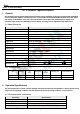
Acer Acer –LCD-X193HQ Through D-SUB/DVI connectors, this unit can support FH= 31~80 KHz, Fv=55~76Hz, Modes details as below: Mode MAC VESA SVGA MAC XGA MAC VESA SXGA VESA WXGA Note: 4.2.1 Resolution (active dot) 640x480@60Hz 640x480@72Hz 640x480@75Hz 640x480@66.66Hz 720x400@70Hz 800x600@56Hz 800x600@60Hz 800x600@72Hz 800x600@75Hz 832x624@74.
Acer Acer –LCD-X193HQ 4 33 00 9A E6 10 00 00 1C 00 00 00 FF 00 30 30 30 5 30 30 30 30 30 30 30 30 30 0A 00 00 00 FD 00 37 6 4C 1F 50 0E 00 0A 20 20 20 20 20 20 00 00 00 FC 7 00 58 31 39 33 48 51 0A 20 20 20 20 20 20 00 39 X193HQ DVI EDID table 0 1 2 3 4 5 6 7 8 9 A B C D E F 0 00 FF FF FF FF FF FF 00 04 72 67 00 00 00 00 00 1 00 00 01 03 80 29 17 78 EA 3D 85 A6 56 4A 9A 24 2 12 50 54 BF
Acer Acer –LCD-X193HQ Items Specification Input impedance ≧ 10K ohm Frequency response range 200Hz – 20kHz Signal to noise ratio ≧ 40 dB Output power ≧ 1.0 W + 1.0 W ( 10%THD ) 5. Function Specifications All the tests to verify specifications in this section shall be performed under the following standard conditions unless otherwise noted. The standard conditions are: Temperature : 25 ± 5°C Warm-up time : 30 minutes minimum Checking display modes : All the specified modes 5.
Acer Acer –LCD-X193HQ A. When OSD isn’t shown on screen, press [MENU] to enter OSD interface. The OSD interface uses “ACER e Color Management” and “User” to instead “Contrast” and “Brightness” separately. When press “ACER e Color Management” to show “e Color OSD”, and press “User” to show OSD interface before. The translations of “ACER e Color Management” and “User” are always English. B. When OSD displays, press [MENU] to perform function of menu icon that is highlight or enter next level menu [MENU] A.
Acer Acer –LCD-X193HQ Brightness 0 ~ 100 User mode 77 Text mode Standard mode Graphics mode Movie mode 44 ACM Image Position Focus Clock H. Position V. Position Warm (6500K) Cool (9300K) Color User 77 97 77 OFF ------------- 0 ~ 100 Depend on each timing 0 ~ 100 50 ○ 1 0 ~ 100 50 0 ~ 100 Depend on each timing Red 0 ~ 100 80 Green 0 ~ 100 80 Blue 0 ~ 100 80 ----- 02.
Acer Acer –LCD-X193HQ 12
Acer Acer –LCD-X193HQ 13
Acer Acer –LCD-X193HQ 14
Acer Acer –LCD-X193HQ 15
Acer Acer –LCD-X193HQ 17
Acer Acer –LCD-X193HQ 18
Acer Acer –LCD-X193HQ 19
Acer Acer –LCD-X193HQ 20
Acer Acer –LCD-X193HQ 22
Acer Acer –LCD-X193HQ 23
Acer Acer –LCD-X193HQ 24
Acer Acer –LCD-X193HQ 25
Acer Acer –LCD-X193HQ 27
Acer Acer –LCD-X193HQ 28
Acer Acer –LCD-X193HQ 29
Acer Acer –LCD-X193HQ 30
Acer Acer –LCD-X193HQ 32
Acer Acer –LCD-X193HQ 33
Acer Acer –LCD-X193HQ 34
Acer Acer –LCD-X193HQ 35
Acer Acer –LCD-X193HQ 36
Acer Acer –LCD-X193HQ 37
Acer Acer –LCD-X193HQ 38
Acer Acer –LCD-X193HQ 40
Acer Acer –LCD-X193HQ 41
Acer Acer –LCD-X193HQ 42
Acer Acer –LCD-X193HQ 43
Acer Acer –LCD-X193HQ 45
Acer Acer –LCD-X193HQ 03 Exploded Diagram 3.1 Screw List Item Part No. Description Qty 1 509146305300R 2 509000000700R BOLT,#4-40x11.8,Ni ROHS 3 509112612500R 4 509216608110R 5 509212606110R 6 509112308100R SCREW,P,CROSS W/WAS,M3*5,Zn ROHS SCREW P T4*12 Zn-BLK ROHS SCREW,F,CROSS,M4*8,Zn, ROHS SCREW,F,CROSS,T4*6,Zn, ROHS(5.8~6.2) SCREW,P,CROSS,T.T-3*8,Z n,ROHS 46 Fixed T(kg*cm) Remark Power Board to 3 4.5~5.0 2 4.0±0.5 D-SUB CON*2 3 8±0.5 Hinge to Stand 4 6.5±0.
Acer Acer –LCD-X193HQ 3.2 .
Acer Acer –LCD-X193HQ 04 Troubleshooting 4.1 No Power & LED Off No power Check primary rectifier voltage Check circuit if short Check IC802, C805, T801, Check F801, P801, RT801, D801 Check pin2 of IC802 voltage about 16V CheckC815,D806, Check primary OVP, OLP and secondary feedback, OVP Check pin1 of IC802 voltage about 9.0V circuit Check R803, R807, R824, R825,R812 Check pin1 of IC802 voltage is below 1.
Acer Acer –LCD-X193HQ 4.2 Unstable Power Unstable power Check sampling Circuit Check R811, R818, R810, R811, R818, R810, R825, Check the C pin voltage of Check the R pin voltage of IC803 about Change IC803 IC803 if 3V Check Check pin2 of IC802 voltage is 16V Check D806 , C815 is hort Change D803 Check pin1 of IC802 voltage below Change R803, R 807 R824, R825, R812 HRN LVDS FFC *1 1.
Acer Acer –LCD-X193HQ 4.3 DC output voltage is unstable Output voltage unstable Check Vbe of Q801below 0.3V Checkcircu it if Check ZD801, D803, D805 Check Q801, Q802 Check reference voltage Check Pin R of IC803 voltage about 2.5V Check R832,, IC801, Check R822, R823.R825 Check feedback circuit Check Vpin2.
Acer Acer –LCD-X193HQ 4.4 No Raster No raster? Yes LED Blue? Yes Backlight can’t be turned on.
Acer Acer –LCD-X193HQ 4.
Acer Acer –LCD-X193HQ 4.6.
Acer Acer –LCD-X193HQ 4.
Acer Acer –LCD-X193HQ 05 Spare parts List ACER PART NO. DESCRIPTION UNIT PRICE (US$) ET.LEH0C.024 55.LEH0J.001 791931300702R PCBA,I/F BOARD,W/SPK,LE18K3-712 ROHS 6.20 1 19.LEH0J.001 791931400700R PCBA,P/I BOARD,W/SPK,LE18K3-712 ROHS 10.00 1 55.LAU0J.002 790061500000R PCBA,KEYPAD BOARD,LE1983-X10 ROHS 1.00 1 50.LEH0J.001 430300802230R HRN ASSY 2x4P to 8P 190mm UL1571#28 0.29 1 50.LEH0J.002 430303001970R HRN LVDS FFC 30P 147MM 0.50 1 50.LBQ0J.
Acer Acer –LCD-X193HQ 06 Schematics and Layouts 6.
Acer Acer –LCD-X193HQ 6.
Acer Acer –LCD-X193HQ 6.
Acer Acer –LCD-X193HQ 6.4 IF BD Layout 6.
5 4 3 2 C820 4700P Y1 C805 68u/450V 7 2 2 3 1 1 Q801 MMBT4401 R835 1.0R 1/2W F802 +5V SB540 4A/125V 1 6 1 R817 D806 6R8 A02 2 9 C812 R829 4.7R C826 1n 500V R825 2.7M R839 150R NC C D808 1N4003 R816 6R8 1 C816 0.1u 100V MEB LTV817M NC 9.1V ZD806 D809 C SN4148 A C818 47u/25V C822 C821 2200P Y1 250V 250V C801-1 R814 1K 10u/16V R IC803 TL431 C824 R818 3.
5 4 3 2 1 D OL2 VIN C516 10p/3KV VIN C510 C509 2.2u/25V NC R520 20K 3 C522 1 R502 100K C502 220p/50V 1 R503 100K OV21 OV2 OV1 LI1 2 LI1 GND LI2 3 LI2 BG 14 VCC 13 SW 12 TG 11 C504 2.2u/16V 4 COMP 5 FT C R505 105K 1% BRIGHTNESS REF R526 NC R504 10K C505 220p/50V C520 3300p/50V 680pF/50V L<2.cm 16 OV1 C508 1u/16V 15 W=2.0mm T501 2 3 FSET 7 BOSC BT 10 8 DBRT VIN 9 C514 NC R506 10 REF 6 8 C513 0.1/50V 5 6 7 C SPW-078 4100-D02 C506 0.
5 4 3 2 1 VCC5V VCC5V GND NC C101 + 100u/16V/NC R101 0/NC C104 R0805 0.1/16V Note 6 PAD U102 LD1117AL-1.8V +3.3V +3.3V 3 +3.3V 5 4 VIN +1.8V 2 VOUT +1.8V 5 D 4 PAD + C106 0.1/16V + C175 NC R199 100 10P 2.0mm D101 SSM24APT DIO--SMA DCR_CONTROL 5 Note 5 R104 0/NC Note 3 U101 LD1117AL-3.3V 3 VIN VOUT 2 1 BRIGHTNESS 5 VOLUME 5 MUTE 5 Note 2 R110 10K ADJ 2 CCFL_ON/OFF C102 100u/16V C105 0.1/16V C103 22u/25V 1 D107 BAT750-LF/NC 3 1 DVI5V ADJ VGA5V +3.
5 1 75 1% 0 R114 75 C113 0.047u/16V 0 R115 75 C114 0.047u/16V 0 R116 75 C115 0.047u/16V C116 10p/50V/NC R159 C117 C118 10p/50V/NC 10p/50V/NC 470 1% R0603 C134 0.047u/16V R122 75 C119 0.047u/16V R123 75 C120 0.047u/16V R124 75 C121 0.047u/16V VGA_DET 2 D103 BAV99 1 2 D104 BAV99 1 2 3 D102 BAV99 1 VCC5V 5 GREEN+ 5 BLUE+ 5 SOG 5 RED- 5 GREEN- 5 BLUE- 5 D105 BAV99 1 VGA_DET R126 0/NC VCC_ESD 2,4 1 C125 0.1/16V/NC 2 C124 0.
5 4 3 2 1 VCC5V DVI5V CN201 DVI-D_CON DVI_RX1DVI_RX1+ R203 R204 10 10 DVI_RX0DVI_RX0+ R205 R206 10 10 DVI_RXC+ DVI_RXC- R207 R208 10 10 SCL SDA VS 6 7 8 DVI_SCL DVI_SDA 5V GND HP RX4RX4+ GND RX3RX3+ RX5RX5+ 14 15 16 4 5 11 12 13 20 21 RX2RX2+ 5 5 RX1RX1+ 5 5 RX0RX0+ 5 5 RXC+ RXC- 5 5 R209 R210 R215 0/NC R211 4K7 D201 BAV70 C201 0.
GND GND C138 22u/25V GND + RXO0RXO0+ RXO1RXO1+ RXO2RXO2+ C153 0.1/16V 60Ω 1 CN107 FFC-CON/NC Note8 C135 0.1/16V C139 1u/16V Note 1 C144 0.1/16V 60Ω Note 1 FB106 2 +1.
Acer Acer –LCD-X193HQ 7.0 Assembly and Disassembly Sequence S1 Ite m P la c e p a n e l S2 A s s e m b le fro n t b e z e l S3 P la c e c h a s s is P h o to P roc e dure s (1 ).T a k e p a n e l o u t o f b o x a n d p la c e it o n th e fo a m . (2 ).T e a r o p e n th e P E b a g a n d p u t it in th e d e s ig n a te d c a rto n . (3 ).P la c e p a n e l o n th e fo a m lik e th e a tta c h e d p ic tu re .
Acer Acer –LCD-X193HQ Assembly and Disassembly (continue) FFC socket S4 Keypad cable socket Insert FFC cabel into mainboard (1).Insert FFC wire into its relevant interface of mainboard properly like attached picture1. (2).Insert the short keypad into its relevant interface like picture (2).Put the fixed mainboard in the right position. 430303001970R HRN LVDS FFC 30P 147MM link main board and power S5 1.
Acer Acer –LCD-X193HQ Assembly and Disassembly (continue) make sure keypad cable into the interface S7 S8 S9 Pack keypad cable Twist Hexagonal screws Assemble chassis keypad cable through chassis 1 2 3 4 Insert the keypad cable into the chassis as picture HRN ASSY 2x4P to 430300802230R 8P 190mm UL1571#28 (1). Handle hexagonal screws and electric opener (2). Twist screw in the interface like the attached Picture1. (3). Place cushion on the designated location after iron frame is taken away.
Acer Acer –LCD-X193HQ Assembly and Disassembly (continue) S10 Insert the FFC cable into the interface of HRN LVDS FFC 430303001970R panel as picture 30P 147MM Insert FFC cable insert FFC bl S11 S12 Insert light cable Insert speaker cable 1)Insert 4pcs light wire into the relevant position 2) put the balance light wire to the position as picture Insert the speaker cabler into the SPEAKER 2W 8Ω interface of power board as picture, make 618100200360R 290&240mm R/G/B sure the red cable in right and
Acer Acer –LCD-X193HQ Assembly and Disassembly (continue) Picture 1 left speaker S13 Assemble speaker picture 2 right speaker Put the right and left speaker into the two SPEAKER 2W 8Ω position of chassis , remark : put the speaker with green cable to left ,and put 618100200360R 290&240mm R/G/B the speaker with red cable to right , you W /CASE can find picture 1and picture 2 picture 1 S14 Insert keypad cable 1) Link keypad cable and keypad as picture1 2) put the ksypad into the interface of front b
Acer Acer –LCD-X193HQ Assembly and Disassembly (continue) S17 S18 Assemble cover hinge Packing 1 2 COVER Put the right and left cover hinge into the 501020225700R HINGE,BLACK related position as picture RIGHT,LE18K3 (1)Release monitor to the packing line (2)Put monitor into carton like the attached picture 57