
Manual


77
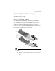
(2) The DIMM D1 to DIMM F2 slots are enabled when a
second CPU is installed on the mainboard.
For the system to function, DIMM modules must be installed following
the slot sequence listed below. DIMM module of the same type, size
and manufacturer must be installed in the same colored DIMM slots.
• CPU 1 - Populate DIMM slots A1 first, followed by slots B1, C1, A2,
B2, and C2.
• CPU 2 - Populate DIMM slots D1 first, followed by slots E1, F1, D2,
E2, and F2.
• To ensure data integrity, use only Acer-approved 240-pin, DDR3
Registered/Unbufferred DIMM ECC modules in 1 GB, 2 GB, 4 GB, or
8 GB capacities.
• Use identical modules—same specification for size, speed, and
organization.
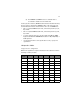
Independent Mode:
Singel processor configuration
Observe the population sequence illustrated in the table below when
installing a memory module.
Tot a l
Capacity
DIMM A2 DIMM A1 DIMM B2 DIMM B1 DIMM C2 DIMM C1
1GB 1GB
2GB 1GB 1GB
3GB 1GB 1GB 1GB
4GB 1GB 1GB 1GB 1GB
6GB 1GB 1GB 1GB 1GB 1GB 1GB
2GB 2GB
4GB 2GB 2GB
6GB 2GB 2GB 2GB
8GB 2GB 2GB 2GB 2GB
12GB 2GB 2GB 2GB 2GB 2GB 2GB