
Desktop PC User's Guide


2 System tour
32
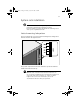
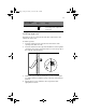
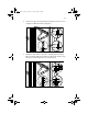
The distance from the center of two holes with closer spacing to the
center of the next pair is equivalent to 1U.
When installing components, you must start your measurement from
the center of the two holes with closer spacing. Otherwise, the screw
holes on the component may not match those on the rack.
Screw types used
The following screws are used in the assembly of the Acer Altos G610
and other rack-mountable components
Screw type and
part number
Figure Usage
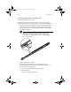
M4 x L5
86.6A536.8R0
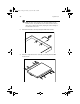
Securing the component rails to
the tray
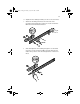
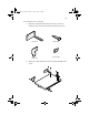
M4 x L8
86.6A536.8R0
Washer
88.21341.605
Nut
87.11042.670
Securing the mounting brackets
to the inner sliding piece
M5 x L5 Securing system components
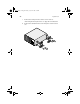
M6 x L10
86.6A52A.100
Securing the cable carrier and
the mounting rails to the rack
Locating ring for
Rack 1024
34.94815.001
Supports the M6 metal screws
for securing server components
to Rack 1024
Locating ring for
Rack 1042
34.94814.001
Supports the M6 metal screws
for securing server components
to Rack 1042
AA G610.book Page 32 Monday, October 22, 2001 9:46 AM