Acer Aspire 1400 Series Service Guide Service guide files and updates are available on the ACER/CSD web; for more information, please refer to http://csd.acer.com.tw PART NO.: VD.A02V5.
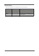
Revision History Please refer to the table below for the updates made on Aspire 1400 service guide. Date IV Chapter Updates 2002/04/11 Ch. 6 Add exploded diagram to Ch.6 2002/04/16 Ch. 3 disassembly flow chart 2002/04/19 Ch. 3 disassembly flow chart 2002/05/13 Ch. 1 p.26 Memory combinations table 2004/01/08 Ch. 1 Revise supported memeory size to 512MB instead of 1GB on page 3 and page 26.
Copyright Copyright © 1999 by Acer Incorporated. All rights reserved. No part of this publication may be reproduced, transmitted, transcribed, stored in a retrieval system, or translated into any language or computer language, in any form or by any means, electronic, mechanical, magnetic, optical, chemical, manual or otherwise, without the prior written permission of Acer Incorporated. Disclaimer The information in this guide is subject to change without notice.
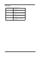
Conventions The following conventions are used in this manual: VI SCREEN MESSAGES Denotes actual messages that appear on screen. NOTE Gives bits and pieces of additional information related to the current topic. WARNING Alerts you to any damage that might result from doing or not doing specific actions. CAUTION Gives precautionary measures to avoid possible hardware or software problems. IMPORTANT Reminds you to do specific actions relevant to the accomplishment of procedures.
Preface Before using this information and the product it supports, please read the following general information. 1. This Service Guide provides you with all technical information relating to the BASIC CONFIGURATION decided for Acer's "global" product offering. To better fit local market requirements and enhance product competitiveness, your regional office MAY have decided to extend the functionality of a machine (e.g. add-on card, modem, or extra memory capability).
VIII
Table of Contents Chapter 1 System Specifications 3 Features . . . . . . . . . . . . . . . . . . . . . . . . . . . . . . . . . . . . . . . . . . . . . . . . . . . . . . . . . . 3 System Block Diagram . . . . . . . . . . . . . . . . . . . . . . . . . . . . . . . . . . . . . . . . . . . . . . . 5 Board Layout . . . . . . . . . . . . . . . . . . . . . . . . . . . . . . . . . . . . . . . . . . . . . . . . . . . . . . 6 Top View . . . . . . . . . . . . . . . . . . . . . . . . . . . . . . . . . . . . . . . . .
Table of Contents Chapter 4 Troubleshooting 69 System Check Procedures . . . . . . . . . . . . . . . . . . . . . . . . . . . . . . . . . . . . . . . . . . . External Diskette Drive Check . . . . . . . . . . . . . . . . . . . . . . . . . . . . . . . . . . . . External CD-ROM Drive Check . . . . . . . . . . . . . . . . . . . . . . . . . . . . . . . . . . . Keyboard or Auxiliary Input Device Check . . . . . . . . . . . . . . . . . . . . . . . . . . . Memory Check . . . . . . . . . . . . . . . . . . . . . .
Chapter 1 System Specifications Features This computer was designed with the user in mind. Here are just a few of its many features: Performance • Intel® Pentium® IV processor with on-die level 2 cache • 256 MB memory expandable to 512MB • High-capacity, Enhanced-IDE hard disk • Lithium-Ion battery pack • Power management system Display The large graphics display offers excellent viewing, display quality and desktop-performance graphics.
Human-centric design and ergonomics ! All-in-one design (CD or DVD, floppy drive, and hard disk) ! Sleek, smooth and stylish design ! Full-sized keyboard ! Wide and curved palm rest ! Ergonomically-centered touchpad pointing device ! Launch keys (supports Audio DJ feature) ! Wireless networking (802.
System Block Diagram Chapter 1 5
Board Layout Top View 6 A-U8 VGA Chip ATI M6-p B-U9 Clock Generator ICS950805AG C-U14 Audio Amplifier Chip TDA0132 D-F1 Fuse E-JP1 LCD Connector F-JP2 Power Button Board Connetor G-JP5 SODIMM Connector H-JP6 Microphone Jack I-JP8 Earphones Jack J-JP7, JP9 Speaker Connector K-JP10 Main Board to Touch Pad Board FFC connector L-JP11 Main Board to Touch Pad Board FPC Connector M-JP12 JP12 Keyboard Connector N-VR1 Audio Volume Control Switch Chapter 1
Bottom View Chapter 1 7
AU10,U13 8 Video DDR SDRAM B-U22 MCH Intel 845 c--U23 CPU Socket D-U30 BIOS ROM 512K8-90 E-U33 ICH2 Intel 82801 F-U40 CARDBUS Controller PCI1420 G-U42 Direct CD-PLay Controller OZ-168T H-U43 AC97 Codec CS-4299 I-U45 KBC/EC PC87951 JU55,U56 USB Power Switch TPS2042DR K-JP13 HDD Connector L-JP14 Parallel Connector M-JP15 CRT Connector N-JP16 S-Video Connector O-JP17 Fan Connector P-JP18 M/B to USB Board Connector Q-JP19 LAN/Modem Connector R-JP20 MINI PCI Connector S-JP21
Outlook View A general introduction of ports allow you to connect peripheral devices, as you would with a desktop PC. Front View # Chapter 1 Icon Item Description 1 Display screen Also called LCD (liquid-crystal display), displays computer output. 2 Power button Turns on the computer power..
10 3 Launch keys Buttons for launching frequently-used programs. You can launch the Internet browser and a set application with launch key. 4 Keyboard Inputs data into your computer. 5 Touchpad Touch-sensitive pointing device which functions like a computer mouse. 6 Click buttons (left and right) The left and right buttons function like the left and right mouse buttons. 7 Palmrest Comfortable support area for your hands when you use the computer.
Left Panel # Icon Item Description 1 Speaker/headphoneout jack Connects to audio line-out devices (e.g., speakers, headphones). 2 Microphone-in jack Ejects the disc from the optical drive. 3 Volume control slider Adjust the volume level. 4 Security keylock Connects to a Kensington-compatible computer security lock. 5 PC Card eject buttons Eject the selected PC Card from its slot. 6 PC Card slots Accepts one Type III or two Type II/I PC Cards.
Right Panel # 12 Icon Item Description 1 Floppy drive Accepts a 3.5-inch diskette. 2 Floppy drive eject button Press to eject the diskette from the floppy drive. 3 Wireless networking button Enables or disables the wireless networking feature. 4 Optical drive Depending on your model: --CD-ROM drive reads CDs. --DVD-ROM drive reads CDs and DVDs. --DVD/CD-RW combo drive reads CDs and DVDs, and writes to CD-Rs and CD-RWs. 5 Optical drive eject button Ejects the disc from the optical drive.
Rear Panel # Chapter 1 Icon Item Description 1 USB ports Connects to USB devices (e.g., USB digital camera). 2 Network jack Connects to an Ethernet 10/100-based network. 3 Modem jack Connects a phone line (only for models with an internal fax/data modem). 4 Parallel portModem jack Connects to a parallel device (e.g., parallel printer). 5 Parallel port Connects to a display monitor. 6 External display port Connects t to a display device with S-video input.
Bottom Panel # 14 Icon Item Description 1 Hard disk bay Houses the computer’s hard disk. 2 Battery bay Houses the computer’s battery pack. 3 Battery release latch Slide and hold to unlatch the battery pack. 4 Memory compartment Houses the computer’s memory upgrade slot.
Indicators The computer has easy-to-read lock indicators (A) found above the keyboard, and status indicators (B) and Audio DJ mode indicators (C) on the front panel of the computer. The status LCD displays icons that show the status of the ocmpouter and its components.. Icon Function Description A. Lock indicators Caps lock Caps Lock is activated. Num lock Numeric Lock (for embedded keypad) is activated. Scroll lock Scroll Lock is activated. Power Lights when the computer is on.
Icon Function Description Battery charge Battery is being charged. Hard disk activity Hard disk is being accessed. Wireless networking Wireless networking feature is enabled. Use the wireless networking switch to enable or disable this feature. See “Right view” on page 6 for the location for the location of this switch. Optical drive activity Optical drive (CD or DVD) is being accessed. Media Player Audio DJ to Microsoft Media Player is set. CD Audio DJ is set to CD playback. C.
Keyboard Lock Keys The keyboard has four lock keys which you can toggle on and off. Lock Key Description Caps Lock When Caps Lock is on, all alphabetic characters typed are in uppercase. Num Lock When Num Lock is on, the embedded keypad is in numeric mode. The keys function as a calculator (complete with the arithmetic operators +, -, *, and /). Use this mode when you need to do a lot of numeric data entry. A better solution would be to connect an external keypad. .
Embedded Numeric Keypad The embedded numeric keypad functions like a desktop numeric keypad. It is indicated by small characters located on the lower edge of the keycaps. The embedded keypad can function in numberic mode or cursor-control mode. Desired Access Number keys on embedded keypad Cursor-control keys on embedded keypad Main keyboard keys 18 Num Lock On Num Lock Off Type numbers in a normal manner. Hold j while typing numbers. Hold j while using cursor-control keys.
Windows Keys The keyboard has two keys that perform Windows-specific functions. Key Windows logo key Application key Chapter 1 Icon Description Start button. Combinations with this key perform special functions. Below are a few examples: + Tab (Activates next taskbar button) + E (Explores My Computer) + F (Finds Document) + M (Minimizes All) j + Windows logo key + M (Undoes Minimize All) + R (Displays Run dialog box) Opens the applications context menu (same as rightclick).
Hot Keys The computer uses hotkey or key combinations to perform functions such as controlling the screen brightness and specifying where to display output. Hot Key Fn-Esc Icon Function Description Speaker toggle Turns the speakers on and off. Fn-n Standby Puts the computer in standby mode. Fn-o Hibernation Puts the computer in hibernation mode.
Keyboard Ergonomics Located below the keyboard, the wide and curved palm rest is ergonomically desinged to provide you with a very comfortable place to rest your hands while you type.
Touchpad The built-in touchpad is a PS/2-compatible pointing device that senses movement on its surface. This means the cursor responds as you move your finger on the surface of the touchpad. The central location on the palm rest provides you optimum comfort and support. Touchpad Basics The following teaches you how to use the touchpad: ! Move your finger across the touchpad to move the cursor.
touchpad is sensitive to finger movements. Hence, the lighter the touch, the better the response. Tapping too hard will not increase the touchpad’s responsiveness.
Launch Keys Located above the keyboard are launch keys that can used to launch applications. NOTE: To configure the launch keys and the applications they launch.. # Icon Item Description 1 WWW By default, launches your Internet browser. 2 Application Launches a set application.
Hardware Specifications and Configurations Processor Item Specification CPU type Intel Desktop P4 up to 1.7GHZ or Northwood upgradable CPU package MPGA478 package CPU CPU core voltage 1.75V/1.5V BIOS Item Specification BIOS vendor Phoenix BIOS Version 1.0 BIOS ROM type Flash ROM BIOS ROM size 512KB BIOS package TSOP Supported protocols ACPI 1.0b,PC Card 95, SM BIOS 2.3, EPP/IEEE 1284, ECP/IEEE 1284 1.7 & 1.9, PCI 2.2, PnP 1.
Memory Combinations Slot 1 Slot 2 Total Memory 128MB/256 MB 0 MB 128MB/256 MB 128MB/256 MB 128 MB 256MB/384 MB 128MB256 MB 256 MB 384MB/512 MB NOTE: Above table lists some system memory configurations. You may combine DIMMs with various capacities to form other combinations. .
Hard Disk Drive Interface Item Specification Disks 1 1 1 1 2 2 Spindle speed (RPM) 4200 RPM 4200 RPM 4200RPM 4200RPM 4200RPM 4200RPM 512KB 2048KB 2048KB 2048KB 2048KB Performance Specifications Buffer size 2048KB Interface ATA-5 ATA-5 ATA-5 ATA-5 ATA-5 ATA-5 Max. media transfer rate (disk-buffer, Mbytes/s) 216 235 287 216 235 287 Data transfer rate (host~buffer, Mbytes/s) 100 MB/Sec. Ultra DMA mode-5 100 MB/Sec. Ultra DMA mode-5 100 MB/Sec.
Audio Interface Item Specification Audio Controller CS 4299 Audio onboard or optional Built-in Mono or Stereo Stereo Resolution 20 bit stereo Digital to analog converter 18 bit stereo Analog to Ditial converter Compatibility Microsoft PC98/PC99, AC97 2.1 Mixed sound source Line-in, CD, Video, AUX Voice channel 8/16-bit, mono/stereo Sampling rate 44.
Parallel Port Item Specification Supports ECP/EPP/Bi-directional (PS/2 compatible) Yes (set by BIOS setup) Note: When Mode is selected as EPP mode, “3BCh” will not be available. Optional ECP DMA channel (in BIOS Setup) DMA channel 1 and 3 Optional parallel port I/O address (in BIOS Setup) 3BCh, 278h, 378h Optional parallel port IRQ (in BIOS Setup) IRQ7, IRQ5 USB Port Item Specification USB Compliancy Level 1.1 OHCI USB 1.
Battery Item Specification Vendor & model name Sony Battery Type Li-ion Pack capacity 57Wh Cell voltage 3.7V/cell Number of battery cell 12 Package configuration 4 cells in series, 3 series in parallel Package voltage 14.8v LCD Inverter Specification This inverter is designed to light up the CCFL of LCD for Aspire 1400 notebook. It should be supported the following LCD panels. No. Supplier Model Type 1 LG LP150x04 TFT, 15.0” XGA 2 Hanstar HSD150PX11-A TFT, 15.
3. Automatic brightness compensation for input voltage variation. Electrical Characteristics No . Parameter 1 Input Symbol Min. Typ. Max. Unit Conditions NV_PWR 9 14.8 21 V Iin -- 0.33 -- A IL 2.7 -- 6.6 mA *Note 1 * Note 2 voltage 2 Input current 3 Lamp current 4 Frequency f 50 55 60KHz KHz 5 Output power Pout -- -- 4.5 W 6 Efficiency η 80% -- -- -- 7 Starting voltage Vs 1500 -- --- V 8 Starting time Tvs 1 -- 2 Sec 9 Dispoff# 2.8 3.3 3.
*2. Inverter operating frequency should be within specification (51-59kHz) at max. and min. brightness load. *3. INV_PWM enable implies INV_PWM signal is High level (On duty cycle is 100%). It it a square wave of 150Hz to adjust backlight brightness that is a function of PWM duty cycle. Backlight brightness is maximum value under INV_PWM at 100% and brightness is minimum under INV_PWM at 40%. *4.The system interface signals belong to 3.3V. *5.
LCD Item Specification Supports colors 262K 262K 262K 262K 262K Brightness control keyboard hotkey keyboard hotkey keyboard hotkey keyboard hotkey keyboard hotkey Contrast control No No No No No Suspend/Standby control Yes Yes Yes Yes Yes Supply voltage for LCD display (V) 3.3 3.3 3.3 3.3 3.
ACPI mode Power Management Mech. Off (G3) All devices in the system are turned off completely. Soft Off (G2/S5) OS initiated shutdown. All devices in the system are turned off completely. Working (G0/S0) Individual devices such as the CPU and hard disk may be power managed in this state.
Mechanical Specification Item Switch Specification Power, Lid, Application/Button Lock/CD-Play, Eject/Stop Button, Play/Pause Button, Reverse Button, Forward Button, Volume Down Button, volume up button Memory Address Map Memory Address 00100000h-000F0000h Size Function 64KB System BIOS 000C0000h-000A0000h 128 KB Video memory (VRAM) 000A0000h-00000000h 640KB Conventional memory 000CD000h-000C0000h VGA BIOS I/O Address Map I/O Address Function 000-00F DMA controller-1 020-021 Interrupt co
IRQ Assignment Map Interrupt Channel IRQ05 Function(Hardware) CardBus Controller IRQ06 Standard Floppy Disk Controller IRQ07 Printer Port (LPT1) IRQ08 Real Time Clock IRQ09 SCI IRQ used by ACPI bus IRQ10 Free IRQ11 Audio Controller, SMBus Controller, Carbus Controller, Intel Network Connection and Modem IRQ12 PS/2 Mouse IRQ13 Numeric data processor IRQ14 Ultra ATA storage Controller Primary IDE controller IRQ15 Ultra ATA storage Controller Secondary IDE channel (CD-ROM drive) DMA Chann
Chapter 2 System Utilities BIOS Setup Utility The BIOS Setup Utility is a hardware configuration program built into your computer’s BIOS (Basic Input/ Output System). Your computer is already properly configured and optimized, and you do not need to run this utility. However, if you encounter configuration problems, you may need to run Setup. Please also refer to Chapter 4 Troubleshooting when problem arises.
Main The Main screen displays a summary of your computer hardware information, and also includes basic setup parameters. NOTE: The screen above is for reference only. Actual values may differ. The table below describes the parameters in this screen. Settings in boldface are the default and suggested parameter settings.. Parameter 38 Description Format/Options System Time Sets the system time. Format: HH:MM:SS (hour:minute:second)System Time. System Date Sets the system date.
Parameter Description Extended Memory Reports the memory size of the extended memory with an integer in the system and 32 Bit SMI will occupy 0.5MB. Note: Extended memory size= Total memory size-1MB-0.5M. BIOS Ver.Product Name Shows the system BIOS version. Format/Options The items in this screen are important and vital information about your computer. If you experience computer problems and need to contact technical support, this data helps our service personnel know more about your computer.
Advanced The Advanced screen contains parameters involving your hardware devices. The table below describes the parameters in the screen Settings in boldface are the default and suggested parameter settings. Parameter 40 Description Options IDE Controller Configures the integrated local bus IDE adapter. Both: Enables CD-ROM and Hard Drive. Primary: Enables Hard Drive only Disabled: Disables the integrated local bus IDE adapter using options.
Parameter Description Options Parallel Port Enables or disables the parallel port. Enabled or Disabled Note: Depending on your operating system, disabling an unused device may help free system resources for other devices. Mode Sets the operation mode of the parallel port. ECP, EPP, Bi-directional or Normal Base I/O address Sets the I/O address for the parallel port. 378/278/3BC Note: When Mode is selected as EPP mode,“3BC” will not be available.
Security The Security screen contains parameters that help safeguard and protect your computer from unauthorized use. The table below describes the parameters in this screen. Settings in boldface are the default and suggested parameter settings. Parameter Description User Password/ Supervisor Password Shows the setting of the user password./ supervisor password. Set User Password Press Enter to set the user password. When set, this password protects the BIOS Setup Utility from unauthorized access.
1. Use the w andy keys to highlight the Set User Password/Set Supervisor Password parameter and press the e key. The Set User Password/Set Supervisor Password box appears: Set SuperVisor Password Enter New Password [ ] Confirm New Password [ ] 2. Type a password in the Enter new password field. The password may consist of up to eight alphanumeric characters (A-Z, a-z, 0-9). Retype the password in the Confirm new password field. 3.
Removing a Password Follow these steps: 1. Use the w and y keys to highlight the Set User Password parameter and press the e key. The Set Password box appears: Set Password Enter Current Password Enter New Password Confirm New Password [ [ [ ] ] ] 2. Type the current password in the Enter Current Password field and press e. 3. Press e twice without typing anything in the Enter New Password and Confirm New Password fields. The computer then sets the User Password parameter to “Clear”. 4.
Others The Others screen contains various parameter settings. The table below describes the parameters in this screen. Settings in boldface are the default and suggested parameter settings. Parameter Description Options Low Battery Alarm Determines whether or not the system will alarm when the battery power is low. Enabled or Disabled Panel Close Alarm Determines whether or not the system will alarm when the display cover is closed.
Boot The Boot screen allows you to set the order in which the system looks for bootable devices on startup. The table below describes these devices. Parameter Description Removable Devices The computer attempts to boot from the removable device (e.g., floppy drive). If unsuccessful, the system goes to the next device in the list. The removable devices include the diskette drive in module bay, the onboard hard disk drive and the CD-ROM in module bay..
Exit The Exit screen contains parameters that help safeguard and protect your computer from unauthorized use. The table below describes the parameters in this screen. Parameter Description Exit Saving Changes Saves changes made and exits the BIOS Setup Utility (same as u ). Exit Discarding Changes Discards changes made and exits the BIOS Setup Utility. Load Setup Defaults Loads default settings for all parameters (same as t ). Discard Changes Discards changes made.
BIOS Phlash Utility The BIOS flash memory update is required for the following conditions: ! New versions of system programs ! New features or options ! Restore a BIOS when it becomes corrupted. Use the Phlash utility to update the system BIOS flash ROM. NOTE: If you do not have a crisis recovery diskette at hand, then you should create a Crisis Recovery Diskette before you use the Phlash utility. NOTE: Do not install memory-related drivers (XMS, EMS, DPMI) when you use the Phlash.
Running Diagnostic Program 1. Test program download Insert TPDL server LAN cable to Aspire 1400 RJ-45 Jack and power on the system via network boot. Download the ASSY/PACK test program image. If you see the message below display on the screen, then the image download is complete. 2. Parallel Port Test Insert PIO loopback to parallel port, then run “PIO.exe” for testing. 3. RTC, FDD Test Insert diskette to floppy disk drive, then run “Compalt.exe” for t test. . 4.
Run “ACR10CFG.bat”. You will see the display below. Then insert USB_Barcode scannner to input the SKU part number in oder to check each SKU configuration. . If the configuration check has no problem, it will go to next test item. If the configuration check fails, the test program will pause and show the error configuration. 5. Touch pad/USB Mouse Test Run “FATMOUSE.exe” to check the touch pad function. Then plug in USB mouse to check its functions.
7. Direct Button Test Run the “BUTTON.exe” to test Audio DJ controls.
8. FAN ON/OFF Test Run the“TEST42.exe”. You may put a feather in front the fan to see if the fan works or not. 9. CD-ROM and Audio Test Insert test CD to CD-ROM drive. Then run “Compalt.exe” to check CD-ROM function. If you hear sounds from left/right speakers, press “p” to next item. If you hear sounds from left/right speakers, then press “P” to pass this test item.
10. Keyboard Test Run “KEY38N2.exe”. Press all keys according to this order--from left to right and from up to down to test each key’s function. If the test is pass then press b + Break to continue next test. 11. Caps/Scroll/Number Lock LED Indicator Test Press keyboard Caps Lock/Num Lk/Fn+Scroll Lk to check LED indicator. 12. Syscard Test (Carbus 32bit) Insert two pieces of Syscard (Card bus) into PCMCIA slots then run “TESTCB.exe” for testing.
13. Battery Charge Test Insert AC adapter to the sytem, then run “591NEW2.exe” for testing.
Chapter 3 Machine Disassembly and Replacement This chapter contains step-by-step procedures on how to disassemble the notebook computer for maintenance and troubleshooting. To disassemble the computer, you need the following tools: ! Wrist grounding strap and conductive mat for preventing electrostatic discharge ! Philips screw driver ! Flat blade screwdriver ! Tweezers Nut screwdriver NOTE: The screws for the different components vary in size.
General Information Before You Begin Before proceeding with the disassembly procedure, make sure that you do the following: 1. Turn off the power to the system and all peripherals. 2. Unplug the AC adapter and all power and signal cables from the system. 3. Remove the battery pack. The two screws that secure the power board LS-1257 on the upper case are M2.5x4. Please make sure you use the right screws.
Disassembly Procedure Flowchart The flowchart on the succeeding page gives you a graphic representation on the entire disassembly sequence and instructs you on the components that need to be removed during servicing. For example, if you want to remove the system board, you must first remove the keyboard, then disassemble the inside assembly frame in that order.
Main Unit Fx7 Ex2 Ex12 Fx5 Logic Upper Logic Lower Ex3 Ex4 LCD Hinge Saddles Disconnect LED board FFC/ Disconnect touchpad FFC Ex2 Speakers Ex5 Ex2 EMI Shielding Ax4 Touchpad Bracket Main Board Ix4 PCMCIA Slot D-sub Bracket Touchpad / Touchpad FFC Heatsink Ex4 Optical Bracket Ex2 Modem Card Hx3 Fan CPU Ex2 Ex1 LED Board Assy Ex4 Touchpad Board Ex2 LED Board Hx4 CPU Support Plate LED Bracket CPU Support Bracket LED Board FFC Touchpad 22pins FFC FDD FFC Screw List Item 58 Descri
Removing the Battery Pack 1. Slide the battery latch to the left. 2. Then remove the battery.
Removing the HDD Module/FDD Module/RAM Door and Optical Drive 60 1. Remove the two screws that secure the HDD module. 2. Then take the HDD module away. 3. Disconnect the FDD FPC. Then turn out the screw that secure the FDD module. Push the FDD module out. 4. Turn out the four screws on the RAM door. Then remove the RAM door. 5. Next, remove the screw that secure the optical drive. Push and take the optical drive away.
Removing the LCD Module/the Power Board and the Keyboard Removing the LCD Module 1. Remove the two (one on each side) screws holding the LCD antenna covers. 2. Then take away the antenna cover. 3. Open the LCD to an angle of 95 degree from the main unit. Then remove the strip cover (middle cover). 4. Turn out the two screws on the rear panel.One on each side. 5. Then remove the two screws on the button panel. One on the left and the other on the right. 6. Remove the screw that secure the EMI bar.
Disassembling the Main Unit Separate the main unit into the logic upper and the logic lower assembly 1. Disconnect the FFC. 2. Disconnect the FDD FPC.. 3. Remove the 7 screws on the upper case. 4. Turn out one screw on the rear panel. 5. Then remove the two (one on each side) screws on the button pane... 6. Remove the 5 screw on the right panel. 7. Then separate the logic upper from the logic lower. Disassembling the logic upper 62 1.
3. Disconnect the LED board FFC. 4. Tear off the aluminum foil on the LEd board. 5. Remove the two screws holding the LED board assembly. 6. Then remove the two screws that secure the LED baord to the LED board bracket. Then you can remove the LED board from the bracket.. 7. Disconnect the LED board FFC. 8. Disconnect touchpad FFC from the touchpad. 9. Slide the touchpad bracket to left then remove the touchpad bracket. Then you can remove the touchpad (with touchpad FFC) from the upper case.
Disassembling the logic lower 1. Pull the Dimm socket with fingers gentlely and take out the memory from the DIMM socket. 2. Release the tape that fasten the speakers’ wire. 3. Disconnect speakers’ wire. 4. Remove the two screws holding the two speakers. One on each side.Then remove the speakers. 5. Remove the two screws that secure the main board. 6. Next, take out the main board from the lower case. 7. Turn out the four screws on the main board. Then remove the optical bracket. 8.
13. Remove the four screws holding the CPU support plate and CPU support bracket. Then remove these two parts from the main board. 14. Turn out the four screws holding the PCMCIA slot and remove it. 15. Remove the four screwlock holding the D-sub bracket to the main board. Then remove the D-sub bracket.
Disassembling the LCD Module 1. Remove the two screwpad then turn out the two screws on the LCD bezel. 2. Disattach the LCD bezel carefully. 3. Unscrew the three screws holding the inverter board. 4. Turn out the six screws that secure the LCD to the LCD panel. 5. Then remove the LCD from the LCD panel. 6. Unfasten the kapton on LCD FPC, then disconnect the LCD FPC and remove it. 7. Disconnect the LCD inverter cable. Then remove the LCD inverter. 8.
Disassembling the External Modules Disassembling the HDD Module 1. Remove the four (two on each side) screws on HDD carrier. Then you can take out the HDD drive from the carrier. 2. Turn out the two screws holding the HDD EMI plate then remove it. 3. Disconnect the hard disk drive connector. Disassembling the Floppy Disk Drive Module 1. Release the kapton that fastens the FDD FPC, then disconnect the floppy disk drive FFC. 2. Unscrew the two screw holding the FDD door. One on each side. 3.
68 Chapter 3
Chapter 4 Troubleshooting Use the following procedure as a guide for computer problems. NOTE: The diagnostic tests are intended to test this model (Aspire 1400 series). Non-Acer products, prototype cards, or modified options can give false errors and invalid system responses. 1. Obtain the failed symptoms in as much detail as possible. 2. Verify the symptoms by attempting to re-create the failure by running the diagnostic test or by repeating the same operation. 3.
System Check Procedures External Diskette Drive Check Do the following steps to isolate the problem to a controller, driver, or diskette. A write-enabled, diagnostic diskette is required. NOTE: Make sure that the diskette does not have more than one label attached to it. Multiple labels can cause damage to the drive or cause the drive to fail. Do the following to select the test device. See “System Diagnostic Diskette” on page 48 for details. 1.
Keyboard or Auxiliary Input Device Check Remove the external keyboard if the internal keyboard is to be tested. If the internal keyboard does not work or an unexpected character appears, make sure that the flexible cable extending from the keyboard is correctly seated in the connector on the main board. If the keyboard cable connection is correct, run the Keyboard Test. See “System Diagnostic Diskette” on page 48 for more details.
Check the Battery Pack To check the battery pack, do the following: From Software: 1. Check out the Power Management in control Panel 2. In Power Meter, confirm that if the parameters shown in the screen for Current Power Source and Total Battery Power Remaining are correct. 3. Repeat the steps 1 and 2, for both battery and adapter. 4. This helps you identify first the problem is on recharging or discharging. From Hardware: 1. Power off the computer. 2.
Power-On Self-Test (POST) Error Message The POST error message index lists the error message and their possible causes. The most likely cause is listed first. NOTE: Perform the FRU replacement or actions in the sequence shown in FRU/Action column, if the FRU replacement does not solve the problem, put the original part back in the computer. Do not replace a non-defective FRU. This index can also help you determine the next possible FRU to be replaced when servicing a computer.
Index of Error Messages Error Code List Error Codes 006 Error Messages Equipment Configuration Error 010 Equipment Configuration Error 070 Real Time Clock Error 1 071 CMOS Battery Bad 4 072 CMOS Checksum Error 1 080 Battery Is Critical Low 1 110 Incorrect password specified, system halted 1 Error Message List Error Messages 74 FRU/Action in Sequence 0200 Failure Fixed Disk Hard disk error detected. Check to see if fixed disk is attached properly.
Error Message List Error Messages FRU/Action in Sequence 02B0 Diskette drive A/B error Drive A: or B: is present but fails the BIOS POST diskette tests. Check the drive is defined with the proper diskette type in BIOS Setup Utility Check if the diskette drive is attached correctly. See “External Diskette Drive Check” on page 70. 02B2 Incorrect Drive A type - run SETUP Type of floppy drive A: not correctly identified in Setup.
Error Message List No beep Error Messages 76 FRU/Action in Sequence No beep, power-on indicator turns off and LCD is blank. Power source (battery pack and power adapter). See “Power System Check” on page 71. Ensure every connector is connected tightly and correctly. Reconnect the DIMM. LED board. Main board. No beep, power-on indicator turns on and LCD is blank. Power source (battery pack and power adapter). See “Power System Check” on page 71.
Index of Symptom-to-FRU Error Message LCD-Related Symptoms Symptom / Error Action in Sequence LCD backlight doesn't work LCD is too dark LCD brightness cannot be adjusted LCD contrast cannot be adjusted Enter BIOS Utility to execute “Load Setup Defaults” on Exit screen, then reboot system. Reconnect the LCD connectors. Keyboard (if contrast and brightness function key doesn't work).
PCMCIA-Related Symptoms Symptom / Error Action in Sequence System cannot detect the PC Card (PCMCIA) PCMCIA slot assembly Main board PCMCIA slot pin is damaged. PCMCIA slot assembly Memory-Related Symptoms Symptom / Error Memory count (size) appears different from actual size. Action in Sequence DIMM Main board Speaker-Related Symptoms Symptom / Error Action in Sequence In Windows, multimedia programs, no sound comes from the computer.
Peripheral-Related Symptoms Symptom / Error Action in Sequence System configuration does not match the installed devices. Enter BIOS Setup Utility to execute “Load Setup defaults”, then reboot system. Reconnect hard disk/CD-ROM/diskette drives. External display does not work correctly. See “System Diagnostic Diskette” on page 48 See if there is an error beep. If there is an erro beep, then change main board. Power off. Then check if RAM CPU BIOS are well-connected.
Intermittent Problems Intermittent system hang problems can be caused by a variety of reasons that have nothing to do with a hardware defect, such as: cosmic radiation, electrostatic discharge, or software errors. FRU replacement should be considered only when a recurring problem exists. When analyzing an intermittent problem, do the following: 80 1. Run the advanced diagnostic test for the main board in loop mode at least 10 times. 2. If no error is detected, do not replace any FRU. 3.
Undetermined Problems The diagnostic problems does not identify which adapter or device failed, which installed devices are incorrect, whether a short circuit is suspected, or whether the system is inoperative. Follow these procedures to isolate the failing FRU (do not isolate non-defective FRU). NOTE: Verify that all attached devices are supported by the computer. NOTE: Verify that the power supply being used at the time of the failure is operating correctly. (See “Power System Check” on page 71): 1.
Index of AFlash BIOS Error Message Error Message 82 Action in Sequence Hardware Error See “System Diagnostic Diskette” on page 48 VPD Checksum Error Reboot the system and then restest with this diskette. BIOS Update Program Error Turn off the power and restart the system. System Error Make sure this AFlash BIOS diskette for this model. Without AC adapter make sure to connect AC adapter Battery Low make sure to install a highly charged battery, and reboot system.
Chapter 5 Jumper and Connector Locations Top View Chapter 5 83
E-JP1 LCD Connector F-JP2 Power Button Board Connetor G-JP5 SODIMM Connector H-JP6 Microphone Jack I-JP8 Earphones Jack J-JP7, JP9 Speaker Connector K-JP10 Main Board to Touch Pad Board FFC connector L-JP11 Main Board to Touch Pad Board FPC Connector M-JP12 JP12 Keyboard Connector SW1 Settings (Lid switch) Setting Switch 1 NONE Switch 2 STAND BY Switch 3 HIBERNATE Switch 4 ON/OFF BUTTON SW2 Settings SW2 POWER BUTTON 84 Setting ON:SYSTEM ON OFF: SYSTEM OFF Chapter 5
Bottom View Chapter 5 85
86 K-JP13 HDD Connector L-JP14 Parallel Connector M-JP15 CRT Connector N-JP16 S-Video Connector O-JP17 Fan Connector P-JP18 M/B to USB Board Connector Q-JP19 LAN/Modem Connector R-JP20 MINI PCI Connector S-JP21 MDC Module Connector T-JP23 SODIMM Connector U-JP25 CDROM Connector V-JP26 PCMCIA Connector W-JP27 USB Connector Chapter 5
Chapter 6 FRU (Field Replaceable Unit) List This chapter gives you the FRU (Field Replaceable Unit) listing in global configurations of Aspire 1400. Refer to this chapter whenever ordering for parts to repair or for RMA (Return Merchandise Authorization). Please note that WHEN ORDERING FRU PARTS, you should check the most up-to-date information available on your regional web or channel. For whatever reasons a part number change is made, it will not be noted on the printed Service Guide.
Exploded Diagram THE SYSTEM 88 Chapter 6
LOGIC UPPER ASSY Aspire 1400 Series Chapter 6 89
LCD 14.
LCD 15” Aspire 1400 Series Chapter 6 91
DVD ASSY 02 Aspire 1400 Series NOTE: The exploded diagrams for CD-ROM, CD-RW, DVD-ROM and DVD-RW module are the same. Therefor, we put only DVD ASSY exploded diagram as your referance. Please also refer to the FRU list below for more information on different models and part numbers. This diagram only explains the relevent location for each part. The part on the exploded diagrams may be different from its actual looks.
FDD ASSY 02 HDD (W/O HDD) ASSY 02 Chapter 6 93
Picture No. Partname And Description Part Number CPU/Processor CPU Willamette 1.7Ghz/400FSB, 256OD 478pin D-0 01.WILAM.1GV Memory 256M SDRAM Mitsubishi MH32S64AVS-6TA-PE 72.03264.AON 256M SDRAM Infineon HYS64V32220GDL-75C2 72.64322.CON 256MB SDRAM APACER 71.84470.111 ASSY LCD MODULE 14.1” XGA AU 6M.A02V5.019 LCD LCD 14.1” and LCD 15” 001-LCD 14.1” and LCD 15” 6M.A02V5.020 ASSY LCD MODULE 15.0” XGA AU 6M.A02V5.021 ASSY LCD MODULE 15.0” XGA HANNSTAR 6M.A02V5.022 ASSY LCD MODULE 15.
Picture No. Partname And Description Part Number 004-LCD 14.1” and LCD 15” LCD PANEL WITH LOGO 60.A02V5.003 005-LCD 14.1” and LCD 15” LCD BEZEL WITH PRINTING-14.1” 60.A02V5.004 LCD BEZEL WITH PRINTING-15.0” 60.A02V5.005 006-LCD 14.1” and LCD 15” COAXIAL CABLE 14.1” AU 50.A02V5.007 COAXIAL CABLE 14.1” SAMSUNG 50.A02V5.008 COAXIAL CABLE 15” XGA AU 50.A02V5.010 COAXIAL CABLE 15”XGA HANNSTAR 50.A02V5.011 COAXIAL CABLE 15” SXGA+ CPT 50.A02V5.012 COAXIAL CABLE 15” SXGA+ HANNSTAR 50.A02V5.
Picture No. 002-FDD ASSY Partname And Description Part Number FDD DOOR MITSUMI 42.A02V5.018 FDD DOOR PANASONIC 42.A02V5.019 NS HDD 2.5 20G IBM CASCADE IC25N020ATCS04-0 07N8325 FW:A71A KH.25202.001 DVD ASSY DVD-ROM MODULE 8X TOSHIBA 6M.A02V5.005 DVD-ROM MODULE 8X MKE 6M.A02V5.006 DVD-ROM MODULE 8X QSI 6M.A02V5.007 HDD/ Hard Disk Drive Optical Drive DVD-RW COMBO MODULE TOSHIBA 6M.A02V5.008 DVD-RW COMBO MODULE TEAC 6M.A02V5.
Picture No. Partname And Description Part Number 005-Logic Upper FPC-FDD LF-1252(M/B TO TOUCHPAD BOARD) 50.A02V5.004 004-FDD ASSY FDD FPC MITSUMI 50.A02V5.005 FDD FPC PANASONIC 50.A02V5.006 POWER CORD CONTINENTAL 27.A02V5.001 NS POWER CORD DANISH 27.A02V5.002 POWER CORD ITALIAN 27.A02V5.003 POWER CORD PRC 27.A02V5.004 POWER CORD SWISS 27.A02V5.005 POWER CORD UK 27.A02V5.006 POWER CORD US 27.A02V5.007 HDD CONNECTOR 22.A02V5.002 POWER BOARD 55.A02V5.
Picture No. Partname And Description Part Number NS MODEM CARD 54.A02V5.001 NS WIRELESS LAN CARD 54.A02V5.002 Adapter NS AS1400 90W DELTA ADAPTER(3-PIN) AP.0201.001 ADAPTER-API AP.0201.002 Battery NS BATTERY LI-ION 12 CELL-SONY BT.A0201.002 BATTERY LI-ION 12 CELL-PANASONIC BT.A0201.001 AS1400 KEYBOARD CHICONY Arabic KB.A0203.010 AS1400 KEYBOARD CHICONY Belgium KB.A0203.012 AS1400 KEYBOARD CHICONY Traditional Chiese KB.A0203.005 AS1400 KEYBOARD CHICONY Czech KB.A0203.
Picture No. Partname And Description Part Number AS1400 KEYBOARD CHICONY Thai KB.A0203.011 AS1400 KEYBOARD CHICONY Turkish KB.A0203.018 AS1400 KEYBOARD CHICONY UK KB.A0203.002 AS1400 KEYBOARD CHICONY US KB.A0203.001 NS MIDDLE COVER 42.A02V5.001 309-The System DIMM COVER 42.A02V5.002 NS HEATSINK COVER 42.A02V5.003 301-The System LOWER CASE W/O SPEAKER-INCLUDING BATTER LATCH, NOB, SPRING 60.A02V5.001 003-Logic Upper UPPER CASE 60.A02V5.002 001-Logic Upper EMI SHIELDING 31.A02V5.
Picture 100 No. Partname And Description Part Number 008-Logic Upper TOUCHPAD BRACKET 33.A02V5.002 311-The System HEATSINK BRACKET 33.A02V5.003 002-Logic Upper LED BRACKET 33.A02V5.004 310-The System D-SUB BRACKET 33.A02V5.005 312-The System CPU SUPPORT BRACKET 33.A02V5.006 006-Logic Upper HINGE SADDLE-R Note: The image includes right and left hinge saddles. 34.A02V5.001 007-Logic Upper HINGE SADDLE-L Note: The image includes right and left hinge saddles. 34.A02V5.
Picture No. Partname And Description Part Number NS BATTERY LATCH SPRING 34.A02V5.003 NS ANTENNA COVER-R Note: The image includes the right and left antenna covers. 42.A02V5.006 NS ANTENNA COVER-L Note: The image includes the right and left antenna covers. 42.A02V5.007 001-HDD (W/O HDD) ASSY HDD CARRIER 42.A02V5.020 005-HDD (W/O HDD) ASSY HDD EMI PLATE 34.A02V5.004 003-DVD ASSY OPTICAL LOCK 22.A02V5.001 001-The System SPEAKER ASSY(R&L) 6K.A02V5.
Picture No. Partname And Description Part Number 313-The System FAN 31.A02V5.003 NS HEATSINK 23.A02V5.001 NS ANTENNA LINE-L 50.A02V5.016 ANTENNA LINE-R 50.A02V5.017 SCREWLOCK, 6NUT 86.A02V5.001 SCREW, M1.7X2.5L 86.A02V5.002 SCREW, TPB 2.0X4 86.A02V5.003 SCREW, M2.5X3 86.A02V5.004 SCREW, M2.5X4 86.A02V5.005 SCREW, M2.5X8 86.A02V5.006 Screws 315-Logic Upper 307-The System 308-The System 002-HDD ASSY 102 SCREW, M2X3 86.A02V5.007 SCREW,M2X4 86.A02V5.008 SCREW, M2X6 86.A02V5.
Chapter 6 103
Appendix A Model Definition and Configuration Aspire 1400 1. Project Name: Compal project 2. Description The Aspire 1400 employs Intel Pentium 4 processor with the reputable Intel 845 chipset that delivers a high performance and professional mobile PC. With powerful multi-media functions, Audio DJ controls and high quality display, it becomes a desktop replacement. Main memory is expandable to 1024MB SDRAM1. Powerful data storage with 1.
Main Features Processor & Core Logic 3 105 ! Intel® Pentium® 4 from 1.7GHz with 256KB L2 cache, up to 2.4GHz with 512KB L2 cache ! Intel® 845 chipset supports 400MHz system bus ! Standard 128/256MB SDRA, upgradeable to 1024MB ! ATI MOBILITY RADEONTM 4x AGP graphic controller with external 16MB DDR ! Simultaneous LCD and CRT display capability ! DualView® support ! Hardware 3D graphics engine ! MPEG-2/DVD hardware-assisted capability ! 20GB or larger Ultra DMA-100 HDD, 1.44 3.
Appendix A 106
Appendix B Test Compatible Components This computer’s compatibility is tested and verified by Acer’s internal testing department. All of its system functions are tested under Windows XP environment. Refer to the following lists for components, adapter cards, and peripherals which have passed these tests. Regarding configuration, combination and test procedures, please refer to the TravelMate a -550 Compatibility Test Report released by the Acer Mobile System Testing Department.
Microsoft Windows XP Environment Test Item Display Specifications ViewSonic PS775 Phillips Brilliance 17” Modem Adapters Modem Xircom Modem WinGlobal CBM56WG LAN 3Com10/100with XJACK connector 3 CXFE575CT LINKSYS Ethernet Card EC2T Multi-Function Xircom RealPort Ethernet 10/100+Modem 56RBE56G Xircom Ethernet 10/100+ Modem 56CBEM56 I/O Peripheral I/O - printer (parallel) HP LaserJet 5P EPSON Stylus 740 I/O - TV Sony KV-W32MX2 I/O - Keyboard Chicony USB keyboard I/O - USB Belkin Express Bus F
Appendix C Online Support Information This section describes online technical support services available to help you repair your Acer Systems. If you are a distributor, dealer, ASP or TPM, please refer your technical queries to your local Acer branch office. Acer Branch Offices and Regional Business Units may access our website. However some information sources will require a user i.d. and password. These can be obtained directly from Acer CSD Taiwan.
110 Appendix C
Index A DIMM Combinations 26 external 60 removing 60 AC Adapter 33 ACPI 1.
L System Utilities 37 System Utility Diskette 48 L2 cache 25 LAN/Modem Combo 26 T M Temperature 34 Test Compatible Components 107 Machine Disassembly 55 Touchpad Check 72 media access Troubleshooting 69 on indicator 15, 16 Memory Check 71 U Model Definition 104 Undetermined Problems 81 Modem 26 USB 29 Modem Combo Card utility external 61 N BIOS 37 V num lock Video 28 on indicator 15, 16 Resolutions 28 O Video controller 29 Online Support Information 109 P W Windows 2000 Environment