
User Guide

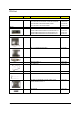

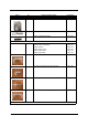
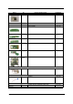
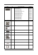

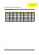

Table Of Contents
- Ch.1 System Specifications
- Ch.2 System Utilities
- Ch.3 Machine Disassembly and Replacement
- General Information
- Disassembly Procedure Flowchart
- Disassembling
- Remove the battery
- Remove the HDD module
- Remove the combo drive
- Remove the thermal module
- Remove CPU
- Remove the memory
- Remove VGA card
- Detach the wireless card
- Remove moden card
- Remove the inverter cover
- Detach the upper system cover
- Remove the LCD module
- Remove the LCD panel
- Remove the inverter board
- Remove the mylars
- Remove the wireless module
- Remove the side bracket
- Remove the LED cable attached on the LCD outer shield.
- Remove the subwoofer
- Release the MDC cable.
- Disconnect the cable to the modem header.
- Remove the keyboard
- Remove the LED board
- Detach the front panel
- Remove the Audio DJ board
- Remove the touch pad
- Remove the touch pad board
- Remove the lid switch cable
- Remove the floppy drive
- Remove the speaker set
- Remove the mainboard
- Remove the system fan
- FDD Module
- HDD Module
- Combo Module
- Re-assembly
- Place the system fan
- Re-assembling the mainboard
- Place the speaker set back to position
- Place the floppy module back to position
- Place the touch pad back to position
- Reconnect the Audio DJ board
- Place the system cover back to position
- Reconnect the LED cable
- Place the keyboard back to position
- Place the MDC cable back to position
- Reconnect the sub-woofer
- Place the LED cable back to position
- Place the side mount back to position.
- Place the wireless antenna back to position
- Reattach the LCD cable
- Place the inverter board back to position
- Re-assembling the LCD module
- Place the system cover and hinge back to position
- Place the inverter cover back to position
- Reconnect the cable to the MDC card and wireless card
- Place the VGA card back to position.
- Insert the memory
- Place the CPU back
- Place the thermal module back to position
- Place the floppy back to position
- Reconnect the HDD power and coaxial cable.
- Place the battery or dummy battery back to position.
- Place the bottom shield back to position.
- FDD Module
- HDD Module
- Combo Module
- Ch.4 Troubleshooting
- Ch.5 Jumper and Connector Locations
- Ch.6 FRU List
- App.A Model Definition and Configuration
- App.B Test Compatible Components
- App.C Online Support Information

27 Chapter 5
LCD BEZEL W/ ACER LOGO 17" 60.A08V7.006
LCD LATCH 17" 47.A08V7.001
LCD SPRING 17" 47.A08V7.002
LCD ACER LOGO 47.A08V7.003
LCD DECORATION BAR 17" 47.A08V7.004
FDD/Floppy Disk Drive
FDD MODULE 1.44MB SLIM PANASONIC JU226A273FC 6M.A08V7.002
FDD 1.44MB SLIM PANASONIC/JU226A273FC KF.22602.001
FDD FFC CABLE 50.A08V7.005
FDD BRACKET 33.A08V7.005
HDD/ Hard Disk Drive
HDD 3.5" 80G U7 5400RPM SEAGATE ST380022A
HDD 3.5" 80G U9 5400RPM SEAGATE ST380012A
HDD 3.5" 120G(L) 7200RPM MAXTOR CALYPSO 6Y120L0
HDD 3.5" 120G 7200RPM SEAGATE CUDA V
KH.38001.003
KH.08001.002
KH.12003.002
KH.31201.001
HDD CABLE, 40PIN 50.A08V7.006
HDD POWER CABLE, 4PIN, IDE 50.A08V7.007
HDD CASE 33.A08V7.006
HDD SCREW 86.A08V7.019
Optical Drive/Combo Drive
Picture No. Partname And Description Part Number