
User Guide
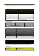
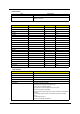
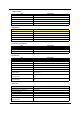
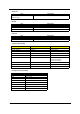
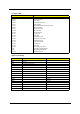
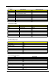
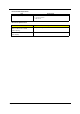
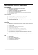
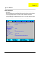
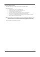
Table Of Contents
- Ch.1 System Specifications
- Ch.2 System Utilities
- Ch.3 Machine Disassembly and Replacement
- General Information
- Disassembly Procedure Flowchart
- Disassembling
- Remove the battery
- Remove the HDD module
- Remove the combo drive
- Remove the thermal module
- Remove CPU
- Remove the memory
- Remove VGA card
- Detach the wireless card
- Remove moden card
- Remove the inverter cover
- Detach the upper system cover
- Remove the LCD module
- Remove the LCD panel
- Remove the inverter board
- Remove the mylars
- Remove the wireless module
- Remove the side bracket
- Remove the LED cable attached on the LCD outer shield.
- Remove the subwoofer
- Release the MDC cable.
- Disconnect the cable to the modem header.
- Remove the keyboard
- Remove the LED board
- Detach the front panel
- Remove the Audio DJ board
- Remove the touch pad
- Remove the touch pad board
- Remove the lid switch cable
- Remove the floppy drive
- Remove the speaker set
- Remove the mainboard
- Remove the system fan
- FDD Module
- HDD Module
- Combo Module
- Re-assembly
- Place the system fan
- Re-assembling the mainboard
- Place the speaker set back to position
- Place the floppy module back to position
- Place the touch pad back to position
- Reconnect the Audio DJ board
- Place the system cover back to position
- Reconnect the LED cable
- Place the keyboard back to position
- Place the MDC cable back to position
- Reconnect the sub-woofer
- Place the LED cable back to position
- Place the side mount back to position.
- Place the wireless antenna back to position
- Reattach the LCD cable
- Place the inverter board back to position
- Re-assembling the LCD module
- Place the system cover and hinge back to position
- Place the inverter cover back to position
- Reconnect the cable to the MDC card and wireless card
- Place the VGA card back to position.
- Insert the memory
- Place the CPU back
- Place the thermal module back to position
- Place the floppy back to position
- Reconnect the HDD power and coaxial cable.
- Place the battery or dummy battery back to position.
- Place the bottom shield back to position.
- FDD Module
- HDD Module
- Combo Module
- Ch.4 Troubleshooting
- Ch.5 Jumper and Connector Locations
- Ch.6 FRU List
- App.A Model Definition and Configuration
- App.B Test Compatible Components
- App.C Online Support Information
16 Chapter 1
APIC mode
NOTE: N - Not be used
PCI x System Devices Add-On-Card Devices
PCI 16 VGA
PCI 17 1394, Carbus
PCI 18 Modem, WLAN (Mini PCI), Audio
PCI 19 LAN
PCI 20 USB 0 (1,1)
PCI 21 USB 1 (1,1)
PCI 22 USB 2 (1,1)
PCI 23 USB 3 (2,0)
DRQ Assignment Map
DRQx System Devices Add-On-Card Devices
DRQ0 N Reserved
DRQ1 LPT (ECP mode) Reserved
DRQ2 FDD N
DRQ3 N Reserved
DRQ4 Cascade N
DRQ5 N Reserved
DRQ6 N Reserved
DRQ7 N Reserved
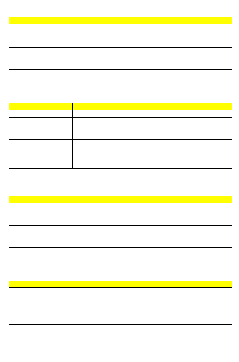
Main Board Major Chips
Item Controller
System core logic SiS650 / SiS962
Video controller SiS650
Super I/O controller SiS962
Audio controller SiS650
LAN controller SiS650
HDD controller Built in SiS650
Keyboard controller Built in SiS650
RTC Built in SiS650
Environmental Requirements
Item Specifications
Temperature
Operating +10 ~ +35°C
Non-operating -20 ~ +60°C (Storage package)
Humidity
Operating 20% to 80% RH
Non-operating 20% to 80% RH
Vibration
Operating (unpacked) 5 ~ 16 Hz: 0.015 mm
16 ~ 250 Hz: 0.21 G