
User Guide
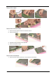
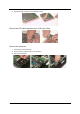
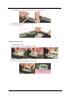
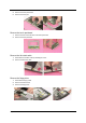
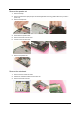
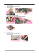
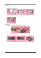
Table Of Contents
- Ch.1 System Specifications
- Ch.2 System Utilities
- Ch.3 Machine Disassembly and Replacement
- General Information
- Disassembly Procedure Flowchart
- Disassembling
- Remove the battery
- Remove the HDD module
- Remove the combo drive
- Remove the thermal module
- Remove CPU
- Remove the memory
- Remove VGA card
- Detach the wireless card
- Remove moden card
- Remove the inverter cover
- Detach the upper system cover
- Remove the LCD module
- Remove the LCD panel
- Remove the inverter board
- Remove the mylars
- Remove the wireless module
- Remove the side bracket
- Remove the LED cable attached on the LCD outer shield.
- Remove the subwoofer
- Release the MDC cable.
- Disconnect the cable to the modem header.
- Remove the keyboard
- Remove the LED board
- Detach the front panel
- Remove the Audio DJ board
- Remove the touch pad
- Remove the touch pad board
- Remove the lid switch cable
- Remove the floppy drive
- Remove the speaker set
- Remove the mainboard
- Remove the system fan
- FDD Module
- HDD Module
- Combo Module
- Re-assembly
- Place the system fan
- Re-assembling the mainboard
- Place the speaker set back to position
- Place the floppy module back to position
- Place the touch pad back to position
- Reconnect the Audio DJ board
- Place the system cover back to position
- Reconnect the LED cable
- Place the keyboard back to position
- Place the MDC cable back to position
- Reconnect the sub-woofer
- Place the LED cable back to position
- Place the side mount back to position.
- Place the wireless antenna back to position
- Reattach the LCD cable
- Place the inverter board back to position
- Re-assembling the LCD module
- Place the system cover and hinge back to position
- Place the inverter cover back to position
- Reconnect the cable to the MDC card and wireless card
- Place the VGA card back to position.
- Insert the memory
- Place the CPU back
- Place the thermal module back to position
- Place the floppy back to position
- Reconnect the HDD power and coaxial cable.
- Place the battery or dummy battery back to position.
- Place the bottom shield back to position.
- FDD Module
- HDD Module
- Combo Module
- Ch.4 Troubleshooting
- Ch.5 Jumper and Connector Locations
- Ch.6 FRU List
- App.A Model Definition and Configuration
- App.B Test Compatible Components
- App.C Online Support Information
58 Chapter 3
Release the MDC cable.
Disconnect the cable to the modem header.
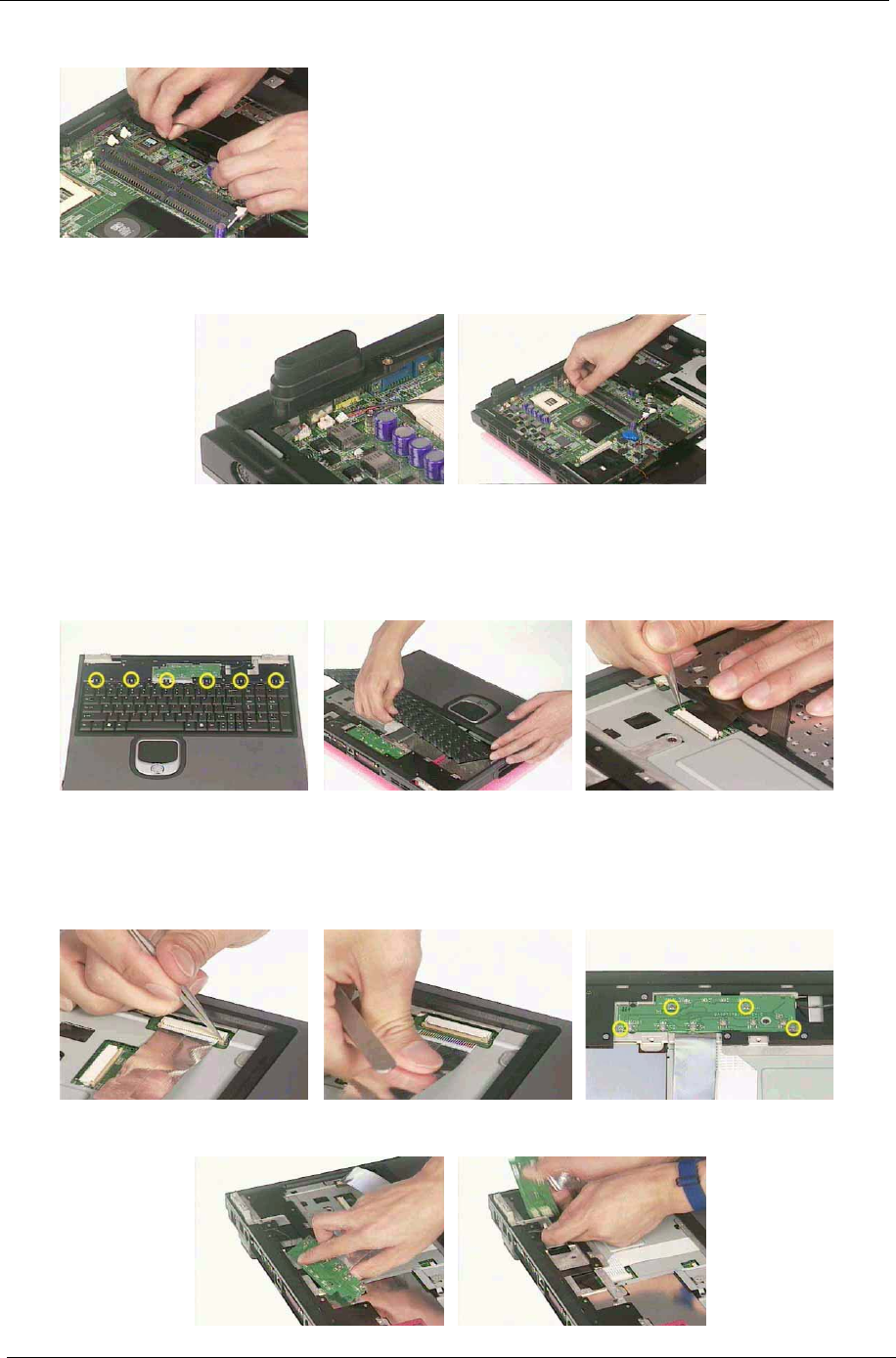
Remove the keyboard
1. Remove the six screws the secure the keyboard.
2. Remove the keyboard and disconnect the attached cable.
Remove the LED board
1. Detach the LED ribbon cable.
2. Remove the four screws that secure the LED board.
3. Lift the LED board and disconnect the LED cable at the same time.