Aspire L5100 Veriton L410 Service Guide Service guide files and updates are available on the AIPG/CSD web; for more information please refer to http://csd.acer.com.
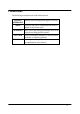
Revision History Please refer to the table below for the updates made on Aspire L5100/Veriton L410 service guide.
Copyright Copyright © 2007 by Acer Incorporated. All rights reserved. No part of this publication may be reproduced, transmitted, transcribed, stored in a retrieval system, or translated into any language or computer language, in any form or by any means, electronic, mechanical, magnetic, optical, chemical, manual or otherwise, without the prior written permission of Acer Incorporated. Disclaimer The information in this guide is subject to change without notice.
Conventions The following conventions are used in this manual: SCREEN Denotes actual messages that appear on screen. MESSAGES NOTE Gives bits and pieces of additional information related to the current topic. WARNING Alerts you to any damage that might result from doing or not doing specific actions. CAUTION Gives precautionary measures to avoid possible hardware or software problems. IMPORTANT Remind you to do specific actions relevant to the accomplishment of procedures.
Preface Before using this information and the product it supports, please read the following general information. 1. This Service Guide provides you with all technical information relating to the BASIC CONFIGURATION decided for Acer's "global" product offering. To better fit local market requirements and enhance product competitiveness, your regional office MAY have decided to extend the functionality of a machine (e.g. add-on card, modem, or extra memory capability).
Chapter 1 System Specifications 1 Features…………………………………………………………………………... 1 Main board Placement……………………………………………………….10 Block Diagram…………………………………………………………………..11 Aspire L5100 Front Panel……..……....…………………….............….12 Aspire L5100 Rear Panel..............……………….………………….…..13 Veriton L410 Front Panel………..........………….......…………….….14 Veriton L410 Rear Panel………..........………........……….……………15 Hardware Specifications and Configurations………......…….…….
Chapter 1 System Specifications Features Operating System Microsoft Windows Vista (Home Basic, Home Premium, Business) Processor Socket Type: AMD AM2 socket processors Processor Type: AMD Sempron 3400+/3500+/3600+/3800+ 35W TDP AMD Athlon64 3500+3800+ 45W TDP AMD Athlon64x2 4000+/4400+/4800+/5000+/5200+ 65W TDP Chipset North Bridge: RS690 (A12) South Bridge: SB600 (A21) 1
PCB Form Factor: Micro ATX Dimension/Layer: 234 x172mm Memory Memory Type: Dual Channel DDR2 667/533, SO-DIMM Support single channel 64 bit mode with maximum memory size up to 2GB Support un-buffered DIMM s only DIMM Slot: 2 Memory Max: 512MB / 2GB DDR2 memory technologies Capacity: 256MB to 1 GB DDR2 533/667 DDR2 SO-DIMM support Graphics ATI RS690 on die graphic solution DVMT 4.
Integrated a DirectX9.0 compliant 2D/3D graphics core Integrated a ATI Radeon X700-based graphics engine PCI PCI Express Slot Type: x16 Support 1x Mini PCIe x1 PCI supported PCI supported IDE interface Single PATA channel support Supports PIO, Multi-word DMA, and Ultra DMA 33/66/100/133 modes Support 1 IDE port SATA Support 2 SATA port, complying with the SATA 2.
Support SATA II 3.0GHz PHY, with backward compatibility with 1.5GHz Audio Audio Type: HD audio codec Audio Channel: 7.1 channel Realtek ALC888-GR,colay with ALC888S(default) Support S/PDIF: S/PDIF-out header (1*4) LAN LAN-RTL 8111C 10/100/1000 Gigabit Controller 10/100/1000BASE-T IEEE 802.3, IEEE802.3u, IEEE802.3ab compliant Support Fully Duplex flow control (IEE 802.3x) Supports pair swap/polarity/skew correction. Wake-on-LAN and remote wake-up support.
USB X9 USB2.0/1.1(Rear 4 ports, Front 5ports/1 for KB wireless receiver, 4 for 40pin B2B header) 1394 1394 header x 1 and Back I/O *1 (TSB43AB23PDTG4 2-port) BIOS BIOS Type: SST 49LF004B FWH 4Mbit symmetrical Flash Note: Boot ROM should be included (PXE function should be built in with default and RPL function is optional by service BIOS) Compliant with latest ASF 2.0 spec Compliant with latest SMT 2.
I/O Connector Controller: Super I/O ITE 8718F-EX with hardware monitor Rear I/O Connector Dual stack USB ports with 1394 connector for 1394 SKU. Dual Stack USB ports for non-1394 SKU. Dual Stack USB ports with RJ-45 connector Vertical Audio connector with 5 JACKS+SPDIF OUT.
PCI slots SATA2 connectors Serial port 2*5 pin connector (2nd serial port) HD audio digital header 4 pin CPU Fan connector 3 pin System FAN connector with linear circuit 1394 header Jumper for clear CMOS Color management for on board connecters (please refer to Acer spec) Header for CIR & IR blaster function (Check ITE Solution) Power Supply Fully supports ACPI states S1,S3,S4,and S5 The Chip Power Management Support state can be achieved by 7
software control bits Hardware controlled intelligent clock gate Support for Cool`n`Quiet via FID/VID change Support for PowerNow Support ATI PowerOnDemand Power On Suspend (POS) or ACPI S1 support Suspend to RAM (STR) or ACPI S3 support Suspend to Disk (STD) or ACPI S4/S5 support Supports C2, C3, and C4 states Provides clock generator and CPU STPCLK# control Supports dynamic lane reduction for the PCI-E interface System Clocks Memory DDR2: PCI 667/533 3
PCI Express 100 MHz USB 48 MHz SIO 48 MHz RTC 32.
Main board Placement 10
Block Diagram 11
Aspire L5100 Front Panel The computer’s front panel consists of the following: Label Description 1 ˦ˣ˘˔˞˘˥ʳˢ˨˧ 2 ˠ˜˖ʳˣ˛ˢˡ˘ 3 ˄ˆˌˇʳˣˢ˥˧˦ 4 ˖˔˥˗ˀ˥˘˔˗˘˥ʳ̃̂̅̇ 5 ˨˦˕ʳˣˢ˥˧˦ 6 POWER BUTTON 7 ˜˥ʳ˟˘˗ 8 LAN LEDʳ 9 ˛˗˗ʳ˟˘˗ʳ 10 ˢ˗˗ʳ˕˨˧˧ˢˡʳ 12
Aspire L5100 Rear Panel Label Description Label Description 1 ˗˖ʳ˽˴˶˾ 9 ˉ˴̈˷˼̂ʳ˽˴˶˾̆ 2 VGA 10 ANTENNA Port 3 ˗˩˜˜ʳ̃̂̅̇ 11 FM Port 4 ˜˥ˀ˕˿˴̆̇˸̅ 12 TV Port 5 LAN PORT 13 AV IN 6 ˢ˕˥ 14 ˧˩ʳˢ˨˧ 7 1394 Port 15 ˦̃˷˼˹ʳˣ̂̅̇ 8 ˨˦˕ʳˣˢ˥˧˦ 13
Veriton L410 Front Panel Label Description 1 POWER BUTTON 2 ˛˗˗ʳ˟˘˗ 3 ˛˗˗ʳ˟˘˗ 4 ˢ˗˗ʳ˟˘˗ 5 ˦ˣ˘˔˞˘˥ʳˢ˨˧ 6 ˠ˜˖ʳˣ˛ˢˡ˘ 7 ˨˦˕ʳˣˢ˥˧˦ʳ 8 ˢ˗˗ʳ˕˨˧˧ˢˡʳ 14
Veriton L410 Rear Panel Label Description Label Description 1 ˢ˕˥ 8 ˗˖ʳ˽˴˶˾ 2 LAN PORT 9 VGA 3 FM Port 10 LINE OUT 4 TV Port 11 ˗˩˜˜ʳ̃̂̅̇ 5 AV IN 12 LINE IN 6 ˧˩ʳˢ˨˧ 13 MIC 7 ˦̃˷˼˹ʳˣ̂̅̇ 14 ˨˦˕ʳˣˢ˥˧˦ 15
Hardware Specifications and Configurations Processor Item Specification Type AMD AM2 socket, Sempron/35W, Athlon64/45W, Athlon64x2 / 65W Socket AMD AM2 socket Minimum operating speed 0 MHz (If Stop CPU Clock in Sleep State in BIOS Setup is set to Enabled.) BIOS Item Specification BIOS code programmer SST 49LF004B FWH BIOS version V6.0 BIOS ROM type SPI Flash BIOS ROM size 4Mb Support protocol PXE 2.1 DMI V.2.0(s)or 2.1 SMBIOS 2.5 ACPI v3.
Main Board Major Chips Item Specification North Bridge RS690 (A12) South Bridge SB600 (A21) APG controller RS690 (A12) Super I/O controller ITE8718 Audio controller Realtek ALC888-GR,colay with ALC888S(default) LAN controller LAN-RTL 8111C HDD controller ITE8718 Keyboard controller ITE8718 Memory Combinations Slot Memory Total Memory Slot 1 256MB, 512MB, 1GB 256MB~1GB Slot 2 256MB, 512MB, 1GB 256MB~1GB Maximum System Memory Supported 256MB~2GB System Memory Item Specification
Audio Interface Item Specification Audio controller ICH7DH Audio controller type Realtek ALC888S Audio channel codec 7.
USB Port Item Specification Universal HCI USB 2.0/1.1 USB Class Support legacy keyboard for legacy mode USB Connectors Quantity Rear connectors: 4 On-board header: 2 (4 USB ports) Environmental Requirements Item Specification Temperature Operating +5°C ~ +35°C Non-operating -20 ~ +60°C (Storage package) Humidity Operating 15% to 80% RH Non-operating 10% to 90% RH Vibration Operating (unpacked) 5 ~ 500 Hz: 2.20g RMS random, 10 minutes per axis in all 3 axes 5 ~500 Hz: 1.
Power Management Function (ACPI support function) Power & Power Management Two power management modes are supported in BIOS: Advanced Configuration and Power Interface (ACPI 2.0) or Advanced Power Management (APM 1.2).
21
Chapter 2 System Utilities The manufacturer or the dealer already configures most systems. There is no need to run Setup when starting the computer unless you get a Run Setup message. The Setup program loads configuration values into the battery-backed nonvolatile memory called CMOS RAM. This memory area is not part of the system RAM. NOTE: If you repeatedly receive Run Setup messages, the battery may be bad/flat. In this case, the system cannot retain configuration values in CMOS.
Entering Setup Power on the computer and the system will start POST (Power On Self Test) process. When the message of “Press DEL to enter SETUP” appears on the screen, press the key of [Delete] to enter the setup menu. NOTE: If the message disappears before you respond and you still wish to enter Setup, restart the system by turning it OFF and On. You may also restart the system by simultaneously pressing [Ctrl+ Alt+ Delete].
The items in the main menu are explained below: Parameter Description Production Information This page shows the relevant information of the main board Standard CMOS Features This setup page includes all the items in standard compatible BIOS Advance BIOS Features This setup page includes all the items of Award special enhanced features Advance Chipset Features This setup page includes all advanced chipset features Integrated Peripherals This setup page includes all onboard peripherals Power Manage
Product Information The screen below appears if you select Product Information from the main menu: The Product Information menu contains general data about the system, such as the product name, serial number, BIOS version, etc. This information is necessary for troubleshooting (maybe required when asking for technical support).
Standard CMOS Setup Select standard CMOS features from the main menu to configure some basic parameters in your system the following screen shows the standard CMOS features menu: 26
The following table describes the parameters found in this menu. Parameter Description Options Date To set the date following the weekday-month-date-year format Week: From [Sun.] to [Sat.]. determined by BIOS and is display only Day: from [1] to [31] (or the maximum allowed in the month. Year: from 1999 to 2099 System Time To set the time following the hour-minute-second format The items format is [hour] [minute][second]. The time is calculated base on the 24-hour timer clock.
Parameter Description Extended Memory Size The BIOS determines how much extended memory is present during the POST. This is the amount of memory located above 1MB in the memory address map of CPU Total Memory Size Total memory size for the system IDE Channel X Master IDE Channel X Slave Hard disk drive connected to channel X master or slave port. To enter the IDE Master or Slave setup, press [Enter].
Advanced Setup The following screen shows the Advanced Setup: The following table describes the parameters found in this menu. Parameter Description Options Hard Disk Boot Priority This features displays the Hard Disk Boot Device priority from high to low and allows users to set the Hard Disk Boot Device Priority. Press [Enter] to enter the setting screen. Use wory to select a device, then press <+> to move it up, or <-> to move it down the list. Press to exit.
Parameter Description Options Virus Warning This feature allows you to enable the VIRUS warning function for IDE Hard Disk boot sector protection. If this function is enabled and there is someone attempts to write data to this area, BIOS will show a warning message on screen and the alarm will beep. [Enabled], [Disabled] Quick Power On Self Test This feature allows the system to skip certain tests while booting.
Advanced Chipset Setup The following table describes the parameters found in this menu. Parameter Description Options Dual Monitor Support This category allows you to enable or disable dual monitor support function [Enabled], [Disabled] Frame Buffer Size This field displays how much frame buffer size of the system. CPU Frequency This field allows you to determine CPU frequency of the system.
Parameter Description Options Spread Spectrum When the system clock generator pulses, the extreme values of the pulse generate excess EMI. Enabling pulse spectrum spread modulation changes the extreme values from spikes to flat curves, thus reducing EMI. This benefit may in some case be outweighed by problems with timing-critical devices, such as a clock-sensitive SCSI device. [Enabled], [Disabled] HT Spread Spectrum Enables or Disables HT Spread Spectrum.
Integrated Peripherals The following table describes the parameters found in this menu. Parameter Description Options IDE Function Setup This page allows you to setup IDE function [Press Enter] Onboard Device Setup This page allows you to setup onboard devices. [Press Enter] Onboard I/O Chip Setup This page allows you to setup onboard I/O chip.
Integrated Peripherals-IDE Function Setup 34
The following table describes the parameters found in this menu. Parameter Description IDE Primary/Second ary Master/Slave PIO The four IDE PIO fields let you set a PIO mode (0-4) for each of the four IDE devices that the onboard IDE interface supports. Modes 0 through 4 provide increased performance. In Auto mode, the system automatically determines the best mode for each device. On-Chip IDE First/Second Channel The Chipset contains a PCI IDE interface with support for two IDE channels.
Parameter Description Options IDE HDD Block Mode Block mode is also called block transfer, multiple commands, or multiple sectors read/write. If your IDE hard drive supports block mode(most new drives do), select Enabled for automatic detection of the optimal number of block read/write per sector the drive can support. [Enabled], [Disabled] SATA PORT Speed Settings This category allows you to determine the speed of SATA port.
The following table describes the parameters found in this menu. Parameter Description Options On Chip USB This field allows you to determine on chip USB type or disable on chip USB. [V1.1+V2.0], [V1.1] UDB Memory Type Use this item to change the type of USB memory to shadow or Base memory. [Shadow], [Base Memory] USB KB Legacy Support This field enables or disables USB keyboard support function. [Enabled], [Disabled] USB Mouse Support This field enables or disables USB mouse support function.
Integrated Peripherals -Onboard I/O Chip Setup 38
The following table describes the parameters found in this menu. Parameter Description Options Onboard FDC Controller Select Enabled if your system has a floppy disk controller (FDC) installed on the system board and you wish to use it. If you install an add-in FDC or the system has no floppy drive, select Disabled in this field. [Enabled]. [Disabled] Onboard Serial Port 1 Select a logical COM port name and matching address for the serial port.
Power Management The Power Management menu lets you configure your system to most effectively save energy while operating in a manner consistent with your own style of computer use.
The following table describes the parameters found in this menu. Parameter Description Options ACPI Function This item allows you to enable or disable the ACPI function [Enabled], [Disabled] ACPI Suspend Type This item specifies the power saving modes for ACPI function. S1 (POSP: The S1 sleep mode is a low power state..
Parameter Description Options Soft-off by PWR/BTTN When Enabled, turning the [Instant-off]: Press down button system off with the on/off then power off instantly button places the system in a [Delay 4 Sec.]: Press Power button 3 very low-power-usage state, sec. to power off. Enter with only enough circuitry suspend if button is receiving power to detect power pressed less than 4 sec. button activity or Resume by Ring activity.
PCI/PnP Setup 43
The following table describes the parameters found in this menu. Parameter Description Options Init Display First Initialize the AGP video display before initializing any other display device on the system. Thus the AGP display becomes the primary display. Reset Configuration Data Normally, you leave this field Disabled.
PC Health Status 45
The following table describes the parameters found in this menu: arameter Description V core Detect system’s voltage status automatically CPU Temperature Detect CPU Temperature automatically CPU/SYSTEM FAN Speed (RPM) Detect CPU/SYSTEM Fan Speed Status automatically CPU Smart FAN Control The item displays the system Smart Fan Function status. It is always enabled by system. Options Frequency/Voltage Control CMOS Setup Utility - Copyright (C) 1985-2005,American Megatrends,Inc.
The following table describes the parameters found in this menu: Parameter Description Optio ns Auto Detect DIMM/PCI CLK This option allows you to enable/disable the feature of auto detecting the clock frequency of the installed PCI bus.
Load Default Settings This option opens a dialog box that lets you install defaults for all appropriate items in the Setup Utility. Parameter Description Load Default Settings Select the field loads the factory defaults for BIOS and Chipset Features, which the system automatically detects. This option opens a dialog box that lets you install optimized defaults for all appropriate items in the Setup Utility.
Set Supervisor/User Password When this function is selected, the following message appears at the center of the screen to assist you in creating a password.
Parameter Description Options Set When this function is selected, the following message Supervisor/User appears at the center of the screen to assist you in Password creating a password. ENTER PASSWORD Type the password, up to eight characters, and press. The password typed now will clear any previously entered password from CMOS Memory. You will be asked to confirm the password. Type the password again and press . You may also press to abort the selection.
Save & Exit Setup Highlight this item and press to save the changes that you have made in the Setup Utility and exit the Setup Utility. Parameter Description Options Save & Exit Setup Press to save the changes that have made in the Setup Utility and exit the Setup Utility. Press to save and Exit or to return to the main menu.
Exit Without Saving Highlight this item and press to discard any changes that you have made in the Setup Utility and exit the Setup Utility.
Chapter 3 Machine Disassembly and Replacement To disassemble the computer, you need the following tools: Wrist grounding strap and conductive mat for preventing electrostatic discharge. Wire cutter. Phillips screwdriver (may require different size). NOTE: The screws for the different components vary in size. During the disassembly process, group the screws with the corresponding components to avoid mismatches when putting back the components.
General Information Before You Begin Before proceeding with the disassembly procedure, make sure that you do the following: 1. Turn off the power to the system and all peripherals. 2.
Disassembly Procedure This section tells you how to disassemble the system when you need to perform system service. Please also refer to the disassembly video, if available. CAUTION: Before you proceed, make sure you have turned off the system and all peripherals connected to it.
Aspire L5100 Standard Disassembly Process Opening the System 1. Place the system unit on a flat, steady surface. 2. Release the screw that shown below. 3. Remove the top cover.
4. As shown pull three button up. 5. Take the belt shown as below. Release this screw first 6. Detach ODD & HDD data and power cable. ODD cable HDD cable 7. Detach HDD date and power cable.
8. Detach HDD SATA Data and power cable attach to MB 9. Detach LED cable. 10. Release four screws as shown below and disconnect the CPU cools.
11. Disconnect the CPU. 12. Remove the Memory. 13. Remove the Video-in cable and TV-out cable. 14. Remove the Front audio cable. 15. Remove the Front card reader cable and Front audio cable.
16.Remove the Video-in cable. 17.Remove the FM cable and TV cable. 18.Remove the SYS_FAN A Cable A&B.
19.Release eight screws then remove the System FAN. 20.Remove the TV Card. 21.Remove the Wireless LAN Cable then release the LAN card.
22.Remove the Audio and Video Board. 23.Remove USB & Audio module. 24.Remove the MB.
63
Veriton L410 Standard Disassembly Process Opening the System 1.Place the system unit on a flat, steady surface. 2.Release the screw that shown below. 3.Remove the top cover.
4.As shown pull three button up. 5.Take the belt shown as below. Release this screw first 6.Detach ODD & HDD data and power cable. ODD cable HDD cable 7.Detach HDD date and power cable.
8.Detach HDD SATA Data and power cable attach to MB 9.Detach LED cable. 10.Release four screws as shown below and disconnect the CPU cools.
11.Disconnect the CPU. 12.Remove the Memory. 13.Remove the Video-in cable and TV-out cable. 14.Remove the Front audio cable.
15.Remove the Front card reader cable and Front audio cable. 16. Remove the Video-in cable. 17. Remove the FM cable and TV cable.
18. Remove the SYS_FAN A Cable A&B. 19. Release eight screws then remove the System FAN. 20. Remove the TV Card.
21. Remove the Wireless LAN Cable then release the LAN card. 22. Remove the Audio and Video Board. 23. Remove USB & Audio module.
24. Remove the MB.
Chapter 4 Troubleshooting Please refer to generic troubleshooting guide for troubleshooting information relating to following topics: Power-On Self-Test (POST) POST Check Points POST Error Messages List Error Symptoms List 72
Chapter 5 Jumper and Connector Information Jumper Setting This section explains how to set jumpers for correct configuration of the main board. Setting Jumper Use the motherboard jumpers to set system configuration options. Jumpers with more than one pin are numbered. When setting the jumpers, ensure that the jumper caps are placed on the correct pins.
74
Chapter 6 FRU (Field Replaceable Unit) List This chapter gives you the FRU (Field Replaceable Unit) listing in global configurations of Aspire L5100/Veriton L410. Refer to this chapter whenever ordering for parts to repair or for RMA (Return Merchandise Authorization). NOTE: Please note WHEN ORDERING FRU PARTS, that you should check the most up-to-date information available on your regional web or channel (http://aicsl.acer.com.
Exploded Diagram LABEL DESCRIPTION 1 BEZEL 2 FRONT IO 3 CHASSIS 4 MOTHERBOARD 5 SLIM ODD 6 ODD AND HDD BRACKET 7 TOP COVER 8 HDD 9 PEDESTAL 76
77
78
Parts Aspire L5100/Veriton L410 79
80
81
82
83
84