
Owner manual

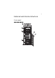
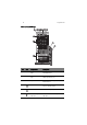
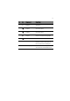
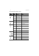

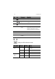
Table Of Contents
- Information for your safety and comfort
- Regulations and safety notices
- 1 System tour
- 2 System setup
- 3 System upgrades
- 4 System BIOS
- 5 System troubleshooting
- Appendix A Server management tools
- Appendix B Rack mount configuration
- Appendix C Acer Smart Console
- Index
1 System tour
8
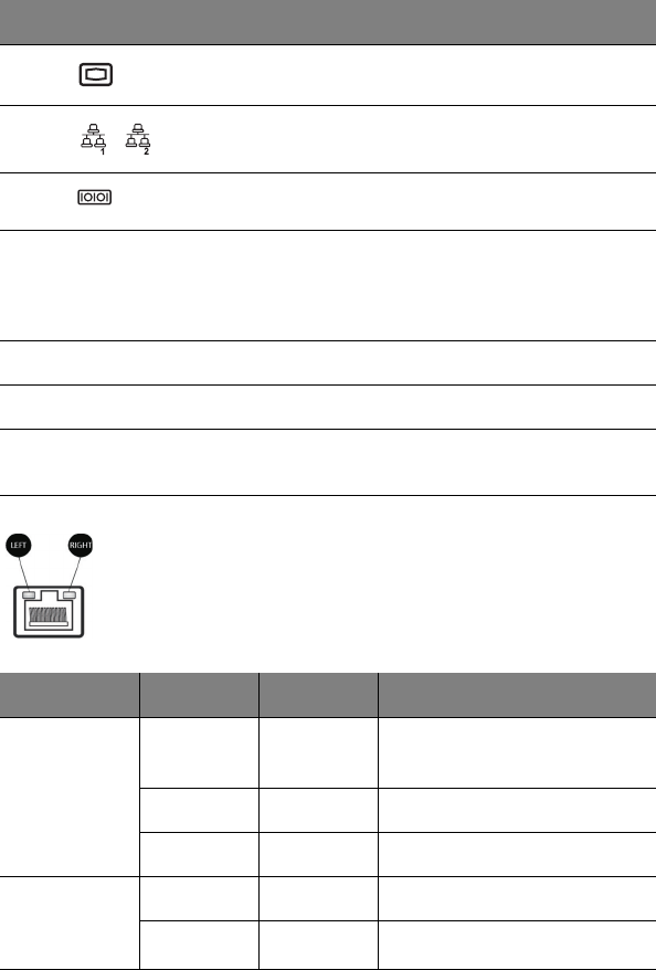
LAN port LED indicator status
6 Monitor port Connects to monitors.
7 Gigabit LAN
port
Connects to an internet or intranet
network.
8 Serial port Connects to serial devices.
9 Rear system ID
switch
Press to mark the server unit within a
server group (when rack mounted) for
purpose of identification during
servicing or maintenance procedures.
10 PCI slot covers Protect the vacant expansion slots.
11 System fans Regulate the system airflow.
12 Power supply
module
Provides power to the system.
LED indicator LED color LED state Status
RJ45 LED
(left)
N/A Off No connection or
10 Mbps
Green On 100 Mbps
Amber On 1000 Mbps
RJ45 LED
(right)
Yellow On Active connection
Yellow Blinking Transmit/Receive activity
No. Icon Component Description