Acer Acer –LCD-D240H Service Manual LCD Monitor Acer D240H
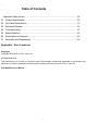
1 Table of Contents Important Safety Notice .........................................................................................02 01 Product Specification ..........................................................................................03 02 Flat Panel Specification .......................................................................................15 03 Exploded Diagram ..............................................................................................
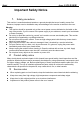
Acer Acer –LCD-D240H Important Safety Notice 1. Safety precautions This monitor is manufactured and tested on a ground principle that a user’s safety comes first. However, improper used or installation may cause damage to the monitor as well as to the user. Warning: This monitor should be operated only at the correct power sources indicated on the label on the rear of the monitor. If you’re unsure of the power supply in you residence, consult your local dealer or Power Company.
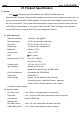
Acer Acer –LCD-D240H 01 Product Specification 1. General: Acer D240H is designed with LVDS interface and VGA/DVI-D/HDMI input, and Embedded DPF Function ,it featured with embedded universal AC power supplies and audio input. It’s a green product and meets all ROHS standard. The power button and display control buttons are on the front of the monitor. The monitors shall automatically to display lower resolution video modes into 1920x1080 full screen display.
Acer Acer –LCD-D240H USB: USB2.0 (optional function) Webcam: 1.0M resolution(1280 x 800), standard USB2.0 interface, array microphone (optional function) 2. Operation Specifications The unit should suffer no visible cosmetic damage and should operate with no degradation in display quality during exposure to the operating conditions and after exposure to the non-operating conditions, in any sequence. 2.
Acer Acer –LCD-D240H Item Electrostatic Discharge Condition Spec Contact discharge: 4KV IEC61000-4-2(EN55024) Contact discharge: 8KV Air discharge : 8KV Air discharge : 15KV ● ● Reliability Items Condition Spec MTBF T=25℃ >50,000 Hours, CCFL Life time Luminance becomes 50% Note 50,000 Hours(Typ) Note1 Note1. Display an all WHITE field at mid Brightness and Contrast settings. 3. Electrical and Optical Characteristics and Performance 3.1 Main Power Supply 3.1.
Acer Acer –LCD-D240H DC output loading capability Vcc5V/1.8A, Vcc25V/1.4A Audio 5V: 1.5A USB 5V: 1.5A <50mS Rise Time Dynamic load change Hold-up time AC input: 100V~240V >10mS Overshoot <10% Turn on delay time 2S Power management See Table-1 Note3: Paralleled a 0.1uF ceramic Cap. And 47uF aluminum Cap. Between the end of DC loading side, Measured band-width=20MHz. Ripple voltage of +25V is less than 1500mv when enter into burst mode. 3.1.
Acer Acer –LCD-D240H CCFL startup voltage ≧2000 Vrms (0˚C) CCFL startup voltage ≧1850 Vrms (25˚C) Operating frequency 40~60 KHz Protect delay time > 1 second Efficiency ≥75% Note: Other panels please refer to the reference panel specs. Brightness output The test to verify specifications in this section shall be performed under the following standard conditions unless otherwise noted.
Acer Acer –LCD-D240H Min. luminance of nine points (backlight) ≥75% Max. luminance of nine points (backlight) 4. Input / Output Signal Specifications 4.1 AC in 4.1.1 AC Input Voltage: 100~240VAC 4.1.2 AC Input Current: 1.2A @100Vac, 0.6A @240Vac 4.1.3 AC Frequency Range: 50~60Hz 4.2 Audio in 4.2.1 Input impedance ﹕ ≧ 10K ohm 4.2.2 Frequency response range ﹕200Hz ~ 10kHz 4.3 USB in (Option) The USB 2.0 includes 4 pins; pin1:VBUS; pin2:DM; pin3:DP; pin4:GND 4.
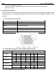
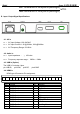
Acer Acer –LCD-D240H 4.5 DVI-D in DVI-D Connector Pin assignment: Pin 1 2 3 4 5 6 7 8 9 10 11 12 13 14 15 Symbol TMDS Data 2TMDS Data 2+ TMDS Data 2/4 shield Pin 16 17 18 19 20 21 22 23 24 DDC Clock DDC Data Analog Vertical Sync TMDS Data 1TMDS Data 1+ TMDS Data 1/3 shield Symbol Hot Plug Detect TMDS Data 0TMDS Data 0+ TMDS Data 0/5 shield Clock shield Clock + Clock - +5V Power GND 4.6 VGA in 4.6.
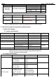
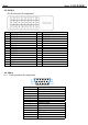
Acer Acer –LCD-D240H 15 4.6.2 DDC SCL Signal SPEC: Items Analog RGB signal Sync H-Sync Frequency V-Sync Frequency Condition Specification Input impedance =75 Ohm 0.7Vp-p Input impedance ≧1k Ohm TTL level, Separate H/V-sync(+/-) 31K~83KHz 49~76Hz 4.7 Timing table VESA MODES Horizontal Mode Resolution Nominal Frequency +/-0.5KHz Sync Polarity Vertical Nominal Frequency +/-1Hz Sync Polarity Nominal Pixel Clock (MHz) 640*480@60Hz 31.469 N 59.941 N 25.175 640*480@72Hz 37.861 N 72.
Acer Acer –LCD-D240H SVGA 832*624@75Hz 49.725 N 74.55 N 57.283 XGA 1152*870@75Hz 68.681 N 75.062 N 100 59.81 P 83.5 Other MODES WXGA Note: 1280*800@60Hz 49.702 N 1. Non-interlace signals only (An interlace signal cannot be display) 2. Please refer to F/W specification for more detail 3.
Acer Acer –LCD-D240H 4.8 HDMI timing table For DVD Player Input, Attached timing is supported : Mode Resolution Pixel Clock MHz H sync KHz V sync Hz Ratio VGA NTSC (480i) NTSC (480p) PAL (576i) PAL (576p) 720p 720p 1080i 1080i 1080P 1080P 640 x 480p 720 x 480 720 x 480 720 x 576 720 x 576 1280 x 720 1280 x 720 1920 x 1080 1920 x 1080 1920 x 1080 1920 x 1080 25.2 13.50 27.00 13.50 27.00 74.25 74.25 74.25 74.25 148.50 148.50 31.5 15.73 31.47 15.63 31.27 37.5 45 28.125 33.72 56.250 67.
Acer Acer –LCD-D240H 4.10.
Acer 1) Nand play photo function: Acer –LCD-D240H 1. without any memory card, the screen will display slideshow photo from Nand storage, 2. If no photo files in Nand storage,the screen will display browser mode. 2) card reader function Connect the USB upstream and the card read function will be started when D240H on Monitor mode..PC will find the two USB devices are CF card and SD/MS/XD/MMC card, the two devices that in the DPF all can be operation by PC 4.11.2.
Acer Acer –LCD-D240H 4.11.4. DPF function test 4.11.4.1. keypad control 1. Switch keypad flow Category Photo ext .jpg .bmp 2.
Acer 3. DPF select photo mode flow 4.
Acer Acer –LCD-D240H
Acer Acer –LCD-D240H Setting menu layer-1
Acer Acer –LCD-D240H Setting menu layer-2 Setting menu layer-3
Acer Acer –LCD-D240H 4.11.4.2. DPF photo function test 1.Test the picture as below items: 1).Photo performance 2). Next picture 3). Forward picture 4). Pause 5). Play 6), slide show. 7). Rotate. 8). Browser small and big photo Check and confirm the function is OK! 2.Test the setting menu as below items: 1),Slideshow time 2). Slideshow effect 3). Auto sleep time 4). Reset 5). Random paly 6), Auto copy 7). Delete all 8). Background color 9). Language Check and confirm the function is OK! 3.
Acer Acer –LCD-D240H 4). If first Monitor mode switch to DPF when AC on and DC on and form power saving ,the screen will display DPF Acer logo 5). If hot_plug any card on DPF mode,the display screen will change to input source select mode . 6). If always press rotate key on play/back mode,the photo will rotate one time. 7). If always press left or right key on browser mode ,if photo less memory range will show the photo else show the last photo 3.
Acer 4.11.5. DPF System Profile 1.DPF-functions overview 2.
Acer Acer –LCD-D240H 5. Function Specifications All the tests to verify specifications in this section shall be performed under the following standard conditions unless otherwise noted. The standard conditions are: Temperature : 25 ± 5°C Warm-up time : 30 minutes minimum Checking display modes : All the specified modes 5.1 Panel general specifications 5.1.1 General specifications Item Describe Supplier AUO Model name M240HW01-V0 Display Area 531.36 × 298.89 Pixel Pitch 276.
Acer Acer –LCD-D240H 6. Function Specifications All the tests to verify specifications in this section shall be performed under the following standard conditions unless otherwise noted. The standard conditions are: Temperature : 25 ± 5°C Warm-up time : 30 minutes minimum Checking display modes : All the specified modes 5.2 Panel general specifications 5.2.1 General specifications Item Describe Supplier AUO Model name M240HW01-V0 Display Area 531.36 × 298.89 Pixel Pitch 276.
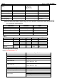
Acer Acer –LCD-D240H Contrast --- --- 0~100 Text mode 44 Standard mode 77 Graphics mode 97 Movie mode 77 User mode 50 Text mode 50 Standard mode 50 Graphics mode 60 Movie mode 56 0~100 50 0~100 50 Focus 0~100 --- Clock 0~100 50 (1) H. Position V. Position --- --- Warm --- --- --- Cool --- --- --- Color Temp User Red 0~100 80 Green 0~100 80 Blue 0~100 80 Auto Configure --- --- --- H. Position --- --- 0~100 Depending on the keypad position V.
Acer Acer –LCD-D240H Reset --- --- --- Resolution --- --- --- H. Freq --- --- --- V. Freq --- --- --- Input Type --- --- --- S/N --- --- --- --(2) Notes: (1) Clock default 50 is for Visa timing. Others depend on timing.
Acer Acer –LCD-D240H 5.4 OSD Translation 5.4.1 Monitor part Main menu (NO_EMEA) English (英语) 繁體中文 Deutsch (德语) Français (法语) Español (西班牙语) Italiano (意大利语) 简体中文 日本語 Picture 畫面 Bild Image Imagen Immagine 画面 ピクチャー Brightness 亮度 Helligkeit Luminosité Brillo Luminosità 亮度 輝度 Contrast 對比 Kontrast Contraste Contraste Contrasto 对比度 コントラスト H.Position 水平位置 H.Position H.Position H.Posicion O.Posizione 水平位置 水平位置 V.Position 垂直位置 V.Position V.Position V.Posicion V.
Acer Acer –LCD-D240H Message menu: (NON_EMEA) English (英语) 繁體中文 Deutsch (德语) Français (法语) Español (西班牙语) Italiano (意大利语) 简体中文 日本語 Auto Config Please Wait 自動調整 請稍待 Autom. Abgl.
English (英语) Acer Russian (俄语) Deutsch (德语) Français (法语) Español (西班牙语) Italiano (意大利语) Dutch (荷兰语) Finnish (芬兰语) Picture Изображ. Bild Image Imagen Immagine Beeld Acer Brightness Helligkeit Luminosité Brillo Luminosità Helderheid Kirkkaus Kontrast Contraste Contraste Contrasto Contrast Kontrasti H.Position H.Position H.Posicion O.Posizione H. positie Vaakasijainti V.Position V.Position V.Posicion V.Posizione V.
Acer Acer –LCD-D240H Standard 標準 Standard Standard Estándar Standard 标准 標準 Text 文字 Text Texte Texto Testo 文本 テキスト Graphics 圖形 Grafiken Images Gráficos Grafica 图形 グラフィック ス Movie 電影 Spielfilm Film Película Film 电影 ムービー User 使用者 Benutzer Utilisateur Usuario Utente 用户 ユーザー Adjust/Exit 調整/結束 Abstimmen/Bee Ajuster/Quitter Ajuste/salir nden Regola/Esci 调节/退出 調整/終了 Select 選擇 Auswahl Seleziona 选取 選択 Sélectionner Seleccionar Main menu (EMEA) Message menu: (EMEA)
Acer Acer –LCD-D240H Monitor Weight 5.6±0.3Kg 6.2 Cabinet Material Cabinet Material Spec Cabinet Plastic Material ABS HB(PMMA) Front Bezel Back Cover Base Cabinet Texture BLACK BLACK BLACK ACER SPECIFICATION 6.3 Mechanical Specification Mechanical Bezel Gap Specification Screen printed Parts Spec ≦1.3mm Front bezel 6.
Acer Acer –LCD-D240H 7. Package 7.1 Unit Package Specification 7.1.1 Units package Items Spec Packaging Refer to ME PACKING SPEC Ink COLOR Length 632+/-2.0mm Height 494+/-2.0mm Width 139+/-2.0mm Gross Weight 7.9±0.3kg Units per Pallet 56sets/pallet 40’ /20’ Container Loading, Palletized 1120sets/560sets 7.1.2 Unit Packing Vibration Testing with vibration shall be done in each of three mutually perpendicular axes.
Acer Acer –LCD-D240H Non operation Thermal Shock Test 7.1.3 7.1.4 Item Description Temperature -200C to 600C Reset cycles times 25ºC>60ºC (10hrs)>25ºC (2hrs)>-20ºC (10hrs)>25ºC 3cycles ,every transition time 0.5 hr, Total cycles 3 cycles Package Drop Drop height (Select drop height according to the gross weight refer to the table at below) 1.0
Acer Acer –LCD-D240H 02.
Product Specification M240HW01 V2 AU OPTRONICS CORPORATION Contents 1.0 Handling Precautions......................................................................................4 2.0 General Description ........................................................................................5 2.1 Display Characteristics ...................................................................................................... 5 2.2 Optical Characteristics.......................................................
Product Specification M240HW01 V2 AU OPTRONICS CORPORATION 1.0 Handling Precautions 1) 2) 3) 4) 5) 6) 7) 8) 9) 10) 11) 12) 13) 14) Since front polarizer is easily damaged, pay attention not to scratch it. Be sure to turn off power supply when inserting or disconnecting from input connector. Wipe off water drop immediately. Long contact with water may cause discoloration or spots. When the panel surface is soiled, wipe it with absorbent cotton or other soft cloth.
Product Specification M240HW01 V2 AU OPTRONICS CORPORATION 2.0 General Description This specification applies to the 24 inch-wide Color a-Si TFT-LCD Module M240HW01.The display supports the Full HD - 1920(H) x 1080(V) screen format and 16.7M colors (RGB 6-bits + Hi-FRC data). All input signals are 2-channel LVDS interface and this module doesn’t contain an inverter board for backlight. 2.
Product Specification M240HW01 V2 AU OPTRONICS CORPORATION 2.2 Optical Characteristics The optical characteristics are measured under stable conditions at 25℃: Item Horizontal CR = 10 (Right) (Left) 150 170 Max. - Vertical CR = 10 (Up) (Down) 140 160 - 600 1000 - Raising Time (TrR) - 3.5 7.5 Falling Time (TrF) - 1.5 2.5 Raising + Falling - 5 10 Red x 0.619 0.649 0.679 Red y 0.308 0.338 0.368 Green x 0.259 0.289 0.319 Green y 0.579 0.609 0.639 Blue x 0.116 0.
Product Specification M240HW01 V2 AU OPTRONICS CORPORATION Note 1: Measurement method The LCD module should be stabilized at given temperature for 30 minutes to avoid abrupt temperature change during measuring (at surface 35℃). In order to stabilize the luminance, the measurement should be executed after lighting Backlight for 30 minutes in a stable, windless and dark room.
Product Specification M240HW01 V2 AU OPTRONICS CORPORATION Note 3: Contrast ratio is measured by TOPCON SR-3 Note 4: Definition of Response time measured by Westar TRD-100A The output signals of photo detector are measured when the input signals are changed from “Full Black” to “Full White” (rising time, TrR), and from “Full White” to “Full Black” (falling time, TfF), respectively. The response time is interval between the 10% and 90% (1 frame at 60 Hz) of amplitudes.
Product Specification M240HW01 V2 AU OPTRONICS CORPORATION CT = | YB – YA | / YA × 100 (%) Where YA = Luminance of measured location without gray level 0 pattern (cd/m2) YB = Luminance of measured location with gray level 0 pattern (cd/m2) Note 9: Test Patern: Subchecker Pattern measured by TOPCON SR-3 RGBRGB Gray Level = L127 RGBRGB Gray Level = L0 RGBRGB Method: Record dBV & DC value with TRD-100 Amplitude AC DC Time AC Level(at 30 Hz) Flicker (dB) = 20 log DC Level document version 1.
Product Specification M240HW01 V2 AU OPTRONICS CORPORATION 3.0 Functional Block Diagram The following diagram shows the functional block of the 24.0 inch Color TFT-LCD Module: LVDS I/F PCB Interface: JAE FI-XB30SSL-HF15 STM MSBKT2407P30HB Mating Type: FI-X30HL (Locked Type) document version 1.
Product Specification M240HW01 V2 AU OPTRONICS CORPORATION 4.0 Absolute Maximum Ratings Absolute maximum ratings of the module are as following: 4.1 TFT LCD Module Item Symbol Min Max Unit Conditions VDD 0 6.0 [Volt] Note 1,2 Item Symbol Min Max Unit Conditions CCFL Current ICFL 3.0 8.0 [mA] rms Note 1,2 Logic/LCD Drive Voltage 4.2 Backlight Unit 4.3 Absolute Ratings of Environment Item Symbol Min. Max.
Product Specification M240HW01 V2 AU OPTRONICS CORPORATION 5.0 Electrical characteristics 5.1 TFT LCD Module 5.1.1 Power Specification Input power specifications are as following: Symbol Parameter Min Typ Max Unit VDD Logic/LCD Drive Voltage 4.5 5.0 5.5 [Volt] IDD1 Input Current - 0.6 1.2 [A] PDD1 VDD Power - 3 6 [Watt] IRush Inrush Current - - 3 [A] VDDrp Allowable Logic/LCD Drive Ripple Voltage - - 300 [mV] p-p Conditions +/-10% VDD= 5.
Product Specification M240HW01 V2 AU OPTRONICS CORPORATION 5.1.2 Signal Electrical Characteristics Input signals shall be low or Hi-Z state when VDD is off. Please refer to specifications of SN75LVDS82DGG (Texas Instruments) in detail.
Product Specification M240HW01 V2 AU OPTRONICS CORPORATION 5.2 Backlight Unit Parameter guideline for CCFL Inverter is under stable conditions at 25℃ (Room Temperature): Parameter Min. Typ. Max. Unit CCFL Standard Current (ISCFL) 7.0 7.5 8.0 [mA] rms CCFL Operation Current (IRCFL) 3.0 7.5 8.
Product Specification M240HW01 V2 AU OPTRONICS CORPORATION Note 2: CCFL standard current is measured at 25±2℃. Note 3: CCFL discharge frequency should be carefully determined to avoid interference between inverter and TFT LCD. Note 4: The frequency range will not affect lamp life and reliability characteristics. Note 5: CCFL inverter should be able to release power that has generating capacity exceeding 2000 volt. Lamp units need minimum voltage, 2000 Volt, for ignition.
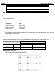
Product Specification M240HW01 V2 AU OPTRONICS CORPORATION 6.0 Signal Characteristic 6.1 Pixel Format Image Following figure shows the relationship of the input signals and LCD pixel format. 1 2 1919 1920 1st Line R G B R G B R GB R G B 1080 Line R G B R G B R GB R G B 6.2 The input data format Note 1: R/G/B data 7:MSB, R/G/B data 0:LSB document version 1.
Product Specification M240HW01 V2 AU OPTRONICS CORPORATION 6.3 Signal Description The module using one LVDS receiver SN75LVDS82(Texas Instruments). LVDS is a differential signal technology for LCD interface and high speed data transfer device. LVDS transmitters shall be SN75LVDS83(negative edge sampling). The first LVDS port(RxOxxx) transmits odd pixels while the second LVDS port(RxExxx) transmits even pixels.
Product Specification M240HW01 V2 AU OPTRONICS CORPORATION Note1: Start from left side Note2: Input signals of odd and even clock shall be the same timing. 6.4 Timing Characteristics Basically, interface timing described here is not actual input timing of LCD module but close to output timing of SN75LVDS82DGG (Texas Instruments) or equivalent.
Product Specification M240HW01 V2 AU OPTRONICS CORPORATION 6.5 Timing diagram Tv M pixel Tdisp(v) Tblk(v) N Line Y Th X DE N RGB Data Invalid Data Line 1 2 3 4 N Line Line Line Line Line Invalid Data CLK Tclk Th Tdisp(h) Tblk(h) DE RGB Data Pixel Pixel Pixel Pixel (Odd) M-7 M-5 M-3 M-1 Invalid Data RGB Data Pixel Pixel Pixel Pixel (Even) M-6 M-4 M-2 M Invalid Data document version 1.
Product Specification M240HW01 V2 AU OPTRONICS CORPORATION 6.6 Power ON/OFF Sequence VDD power and lamp on/off sequence are as follows. Interface signals are also shown in the chart. Signals from any system shall be Hi-Z state or low level when VDD is off. Value Parameter Typ. Max. T1 0.5 - 10 [msec] T2 0 - 15 [msec] T3 300 - - [msec] T4 200 - - [msec] T5 0 16 50 [msec] T6 - - 100 [msec] T7 1000 - - [msec] document version 1.0 NUMPAGES |29} Unit Min.
Product Specification M240HW01 V2 AU OPTRONICS CORPORATION 7.0 Connector & Pin Assignment Physical interface is described as for the connector on module. These connectors are capable of accommodating the following signals and will be following components. 7.1 TFT LCD Module Connector Name / Designation Interface Connector / Interface card STM Manufacturer JAE Type Part Number Mating Housing Part Number MSBKT2407P30HB FI-XB30SSL-HF15 FI-X30HL (Locked Type) 7.1.
Product Specification M240HW01 V2 AU OPTRONICS CORPORATION 7.2 Backlight Unit Physical interface is described as for the connector on module. These connectors are capable of accommodating the following signals and will be following components. Connector Name / Designation Lamp Connector / Backlight lamp Manufacturer CVILUX Type Part Number CP0502SL090 Mating Type Part Number CP0502P1ML0 7.2.1 Signal for Lamp connector Connector No. CN1 Upper CN2 Connector No. CN3 Lower CN4 document version 1.
Product Specification M240HW01 V2 AU OPTRONICS CORPORATION 8.0 Reliability Test Environment test conditions are listed as following table. Items Required Condition Temperature Humidity Bias (THB) Ta= 50℃, 80%RH, 300hours High Temperature Operation (HTO) Ta= 50℃, 50%RH, 300hours Low Temperature Operation (LTO) Ta= 0℃, 300hours High Temperature Storage (HTS) Ta= 60℃, 300hours Low Temperature Storage (LTS) Ta= -20℃, 300hours Vibration Test (Non-operation) Acceleration: 1.
Product Specification M240HW01 V2 AU OPTRONICS CORPORATION 9.0 Shipping Label The label is on the panel as shown below: Note 1: For Pb Free products, AUO will add for identification. Note 2: For RoHS compatible products, AUO will add for identification. Note 3: For China RoHS compatible products, AUO will add for identification. Note 4: The Green Mark will be presented only when the green documents have been ready by AUO Internal Green Team. document version 1.
10.0 Mechanical Characteristics Ver 0.
Ver 0.
Ver 0.
Acer Acer –LCD-D240H 03 Exploded Diagram 3.1 D240H_SCREW_LIST ITEM 1 2 3 4 PN 509146306 200R 509216608 110R 509412610 500R 509000000 700R Description Q'T Fixed Y(P T(kg*cm) CS) SCREW,P,CROSS,W/WAS, 10 M3*6,Zn-Cc SCREW,F,CROSS,M4*8,BL 4 ACK,NL,ROHS(NYLOK) SCREW B CROSS T T-4*10 3 BLK ROHS BOLT,#4-40x11.8,Ni 3.2. LCD Exploded drawing (All) 4 Remark 6.5±0.5 For NVBD/PWRBD/HDMI 12±1 For Hingle toBack cover 9.5±0.5 For Hingle to Stand Front 4.0±0.
Acer Acer –LCD-D240H 04 Troubleshooting 4.
Acer Acer –LCD-D240H 4.
Acer Acer –LCD-D240H 4.
05 Spare parts List ACER PART NO. OEM PART NO DESCRIPTION 55.LJR0J.001 792381300720H PCBA,IF/B(V2,W/SPK,EMEA),LP2441-737 55.LJR0J.002 792381400710H PCBA,PI/B,W/SPK,LP2441-737 55.LEW0J.003 792381500000R PCBA,POWER KEYPAD/B,LP2441 ROHS 55.LEW0J.004 792381500010R PCBA,TOUCHPAD BOARD,LP2441 ROHS 55.LJR0J.003 792382400700H PCBA,CARD BOARD,LP2441-737 50.LEW0J.002 430303002230R HRN LVDS FFC 30P 166.5mm W/TASTE 50.LEW0J.003 430300400390R HRN ASS'Y 4P 27MM UL1571#28 50.LE40J.
60.LEW0J.002 714030022100R ASSY BEZEL ,LP2441 60.LEW0J.003 714011206200R ASSY STAND ,LP2441 60.LEW0J.004 714020018200R ASSY BASE,LP2441 60.LJR0J.002 701000018401R ASSY CHASSIS,DPF,LP2441 60.LEW0J.005 501020228600R HINGE COVER,LEFT , LP2441 60.LEW0J.006 501020228601R HINGE COVER,RIGHT , LP2441 23.LFV0J.001 618100200430R SPEAKER 2.5W4Ω 230mm&210mm R/G/B W/CASE LK.24005.019 631102240240H LCP 24"M240HW01-V2-00(A)(AUO)HF LK.24005.
Acer Acer –LCD-D240H 06 Schematics and Layouts 6.
Acer 6.
Acer Acer –LCD-D240H
Acer 6.
Acer 6.4 Touchpad BD Layout 6.
Acer 6.
5 4 sd/ms/xd_33V CF_RST CF_IORDY CF_DMARQ CF_DMACK CF_INTRQ 38 13 VCC VCC XD_REN/C pull up GPF20 XD_WEN/C pull down GPF15 GPF16 20 19 18 17 16 15 14 12 11 10 8 A0 A1 A2 A3 A4 A5 A6 A7 A8 A9 A10 XD_BSY/C XD_WPn/C pull up GPF18 GPF21 XD_CE0 XD_CD pull up GPC12 MS_INS 7 32 CS0 CS1 40 33 VS2# VS1# 25 26 CD2 CD1 9 34 35 36 39 41 42 43 44 45 46 24 37 ATASEL# IORD# IOWR# WE# CSEL# RESET# IORDY INPACK# REG# DASP# PDIAG# IOCS16# INTRQ SD0_CLK MS_CLK MS_D2 MS_D3 MS_D4 MS_D5 MS_D6 MS_D7 R
07 Assembly and Disassembly S1: Take out a panel S3: Take out a chassis on the panel and assemble the power board and the chassis S2: Assemble the panel and the bezel. S4: Take out the main board and insert the FFC cable and keypad cable.
S5: Assemble the main board and the Card board with the chassis. S7: Use a screwdriver to screw the 4 screws to fix the main board and USB board. MAIN BOARD Card BOARD 2 1 S6: Use a screwdriver to screw the 5 screws to fix the power board. 4 S8: Use a screwdriver to screw the 1 screw to fix the HDMI connecter.
S9: Use a screwdriver to screw the 4 screws S11: Set up the speaker. to fix the VGA and DVI connecter. Red left and green right 1 2 3 4 S10: Fix the chassis in the bezel. S12: Release the LVDS cable between main board and panel. a S12: Set up the keypad board and the touchpad board.
S13: Fix the touchpad board and the keypad board. Connect the two board S15: Assemble the stand and fix it. 1 4 S14: Assemble the back cover. 2 2 3 3 4 3 S16: Assemble the left and right hinge cover.
S17: Assemble the base with the stand.