730sg-1.book Page I Wednesday, December 1, 1999 6:03 PM TravelMate 730 Service Guide Service guide files and updates are available on the AIPG/CSD web; for more information, please refer to http://csd.acer.com.tw PART NO.: 49.49C02.001 DOC. NO.
730sg-1.book Page II Wednesday, December 1, 1999 6:03 PM Copyright Copyright © 1999 by Acer Incorporated. All rights reserved. No part of this publication may be reproduced, transmitted, transcribed, stored in a retrieval system, or translated into any language or computer language, in any form or by any means, electronic, mechanical, magnetic, optical, chemical, manual or otherwise, without the prior written permission of Acer Incorporated.
730sg-1.book Page III Wednesday, December 1, 1999 6:03 PM Conventions The following conventions are used in this manual: Screen messages Denotes actual messages that appear on screen. NOTE Gives bits and pieces of additional information related to the current topic. WARNING Alerts you to any damage that might result from doing or not doing specific actions. CAUTION Gives precautionary measures to avoid possible hardware or software problems.
730sg-1.book Page IV Wednesday, December 1, 1999 6:03 PM Preface Before using this information and the product it supports, please read the following general information. IV 1. This Service Guide provides you with all technical information relating to the BASIC CONFIGURATION decided for Acer's "global" product offering. To better fit local market requirements and enhance product competitiveness, your regional office MAY have decided to extend the functionality of a machine (e.g.
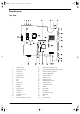
730sg-1.book Page V Wednesday, December 1, 1999 6:03 PM Table of Contents Chapter 1 System Specifications 1 Features. . . . . . . . . . . . . . . . . . . . . . . . . . . . . . . . . . . . . . . . . . . . . . . . . . . . . . . . 1 System Block Diagram . . . . . . . . . . . . . . . . . . . . . . . . . . . . . . . . . . . . . . . . . . . . 3 Board Layout . . . . . . . . . . . . . . . . . . . . . . . . . . . . . . . . . . . . . . . . . . . . . . . . . . . . 4 Top View . . . . . . . . . . . . . . . . . . . .
730sg-1.book Page VI Wednesday, December 1, 1999 6:03 PM Table of Contents Removing the Audio Jack Cover . . . . . . . . . . . . . . . . . . . . . . . . . . . . . . . . Removing the PCMCIA Socket . . . . . . . . . . . . . . . . . . . . . . . . . . . . . . . . . Removing the Modem Power Cable . . . . . . . . . . . . . . . . . . . . . . . . . . . . . Disassembling the LCD Module . . . . . . . . . . . . . . . . . . . . . . . . . . . . . . . . . . . . Removing the LCD Bezel. . . . . . . . . . . . . . . . . . .
30sg-1.book Page 1 Wednesday, December 1, 1999 6:03 PM Chapter 1 System Specifications Features This computer was designed with the user in mind.
730sg-1.book Page 2 Wednesday, December 1, 1999 6:03 PM Display The large graphics display offers excellent viewing, display quality and desktop performance graphics. The computer supports a Thin-Film Transistor (TFT) liquid crystal display (LCD) displaying 24-bit high-color at 1024x768 Extended Graphic Array (XGA) resolution. Video performance 2X AGP video graphic accelerator with 8 MB of video memory boost video performance.
730sg-1.
730sg-1.
730sg-1.
730sg-1.book Page 6 Wednesday, December 1, 1999 6:03 PM Panel Ports allow you to connect peripheral devices to your computer as you would with a desktop PC. Left Panel # 6 Icon Port Connects to... 1 Infrared port Infrared device (e.g., infrared printer, IRaware computers) 2 PC Card slot 16-bit PC Cards and 32-bit CardBus PC Cards (ZV support) 3 Speaker-out jack Speakers or headphones 4 Audio line-in jack Audio line-in device with a 3.5mm mini jack (e.g.
730sg-1.book Page 7 Wednesday, December 1, 1999 6:03 PM Rear Panel # Chapter 1 Icon Port Connects to... 1 DC-in jack AC adapter and power outlet 2 PS/2 port PS/2-compatible devices (e.g., PS/2 keyboard/mouse/keypad) 3 Modem jack Phone line (only for models with an internal fax modem) 4 Serial port Serial devices (e.g., serial mouse) 5 Parallel port Parallel devices (e.g., parallel printer) 6 Network jack Ethernet-based network 7 USB port USB devices (e.g.
730sg-1.book Page 8 Wednesday, December 1, 1999 6:03 PM Bottom Panel # 1 8 Icon Port Connects to...
730sg-1.book Page 9 Wednesday, December 1, 1999 6:03 PM Right Panel 1 2 Chapter 1 3 # Icon 1 N/A Notebook Camera Port Connects to...
730sg-1.book Page 10 Wednesday, December 1, 1999 6:03 PM Indicators The computer has six easy-to-read status icons on the right of the display screen. The Power and Standby status icons are visible even when you close the display cover so you can see the status of the computer while the cover is closed. # 1 Icon Function Power Description Lights when the computer is on. Blinks when a battery-low condition occurs. 2 Sleep Lights when the computer enters Sleep mode.
730sg-1.book Page 11 Wednesday, December 1, 1999 6:03 PM Hot Keys The computer employs hot keys or key combinations to access most of the computer’s controls like screen contrast and brightness, volume output and the BIOS Utility. To activate hot keys, press and hold the Fn key before pressing the other key in the hot key combination. Hot Key Icon Function Description Fn-F1 Hotkey help Displays a list of the hotkeys and their functions. Fn-F2 Setup Accesses the notebook configuration utility.
730sg-1.
730sg-1.fm Page 13 Saturday, August 12, 2000 10:59 AM System Memory Item Specification Supports DIMM type Synchronous DRAM Supports DIMM Speed 100MHz Supports DIMM voltage 3.3V Supports DIMM package 144-pin DIMM Memory module combinations You can install memory modules in any combinations as long as they match the above specifications.
730sg-1.fm Page 14 Saturday, August 12, 2000 10:59 AM Modem Interface Item Specification Modem connector location Rear side Floppy Disk Drive Interface Item Specification Vendor & model name Mitsumi D353G Floppy Disk Specifications Media recognition 2DD (720KB) 2HD (1.2MB, 3-mode) 2HD (1.44MB) Sectors/track 9 15 18 Tracks 80 80 80 Data transfer rate (Kbit/s) 1 MB 1.
730sg-1.fm Page 15 Saturday, August 12, 2000 10:59 AM CD-ROM Interface Item Specification Access time (typ.) 200 msec. (typ.
730sg-1.book Page 16 Wednesday, December 1, 1999 6:03 PM Video Interface Item Specification Chip vendor ATI Chip name Rage Mobility-M1 Chip voltage Core/2.5V Memory/3.3V Supports ZV (Zoomed Video) port Yes Graph interface 2X AGP (Accelerated Graphics Port) bus Maximum resolution (LCD) 1024x768 (24 bit colors) Maximum resolution (CRT) 1024x768 (24 bit colors) Video Memory Item Specification Fixed or upgradeable Fixed, built-in video controller Video memory size 8.
730sg-1.book Page 17 Wednesday, December 1, 1999 6:03 PM Serial Port Item Specification Serial port controller NS PC97338VJG Number of serial port 1 Supports 16550 UART Yes Connector type 9-pin D-type connector, in male type Location Rear side Serial port function control Enable/Disable by BIOS Setup Optional serial port (in BIOS Setup) 3F8h, 3E8h, 2E8h Optional serial port IRQ (in BIOS Setup) IRQ4, IRQ11 USB Port Item Specification USB Compliancy Level 1.0 OHCI USB 1.
730sg-1.book Page 18 Wednesday, December 1, 1999 6:03 PM Keyboard Item Specification Internal & external keyboard work simultaneously Yes Battery Item Specification Vendor & model name Sony Battery Type Li-ion Pack capacity 5400 mAH Cell voltage V/cell Number of battery cell 9 Package configuration 3 cells in series, 3 series in parallel Package voltage 11.1 V DC-AC LCD Inverter Item Specification Vendor & model name Ambit T62.123.C.01 Input voltage (V) 7.3 (min.
730sg-1.book Page 19 Wednesday, December 1, 1999 6:03 PM LCD Item Specification Supply voltage for LCD display (V) 3.3 3.3 3.3 3.3 Supply voltage for LCD backlight (Vrms) 601 650 670 690 AC Adapter Item Vendor & model name Specification Delta ADT-60XB D 3P Input Requirements Maximum input current (A, @90Vac, full load) 1.5 A 0.
730sg-1.book Page 20 Wednesday, December 1, 1999 6:03 PM Power Management Power Saving Mode Standby Mode Waiting time specified by the System Standby value or the operating system elapses without any system activity. T T Phenomenon The buzzer beeps The Sleep indicator lights up Or When the computer is about to enter Hibernation mode (e.g., during a battery-low condition), but the Hibernation file is invalid or not present.
730sg-1.
730sg-1.
730sg-1.book Page 23 Wednesday, December 1, 1999 6:03 PM Chapter 2 System Utilities BIOS Setup Utility The BIOS Setup Utility is a hardware configuration program built into your computer’s BIOS (Basic Input/ Output System). Your computer is already properly configured and optimized, and you do not need to run this utility. However, if you encounter configuration problems, you may need to run Setup. Please also refer to Chapter 4 Troubleshooting when problem arises.
730sg-1.book Page 24 Wednesday, December 1, 1999 6:03 PM If you would like to keep the changes you made, use the cursor left/right (→←) keys to select Yes; then press Enter. Choose No if you want to discard the changes you made. System Information The System Information sub-menu displays basic and important information about your computer. System Information CPU Type & Speed ................ Pentium III, 450 MHz (Coppermine) Floppy Disk Drive ............... 1.44 MB 3.5-inch System with ................
730sg-1.book Page 25 Wednesday, December 1, 1999 6:03 PM Parameter Description Product Name Shows the official name of the product “brand name + model name”. The default setting is TravelMate 730. Product name will be stored in LCD inverter. Manufacturer Name Shows the name of the manufacturer and stored in LCD inverter. The default setting is Acer. UUID Shows the universally unique identifier number of the computer, also known as GUID (Globally Unique Identifier).
730sg-1.book Page 26 Wednesday, December 1, 1999 6:03 PM Startup Configuration The Startup Configuration sub-menu contains parameter values that define how your computer behaves on system startup. Startup Configuration Boot Display .................... [Auto] / [Both] Screen Expansion ................ [Disabled] / [Enabled] Resume on LAN Access ............ [Disabled] / [Enabled] Hotkey Beep ..................... [Enabled] / [Disabled] Fast Boot .......................
730sg-1.book Page 27 Wednesday, December 1, 1999 6:03 PM Setting the Boot Drive Sequence The Boot Drive Sequence section lists boot priorities (1st, 2nd and 3rd) for bootable drives in your computer. For example, the default value (1st:Hard Disk, 2nd:Floppy Disk, and 3rd:CD-ROM, DVD-ROM) tells the computer to first search for a hard disk. If it finds one present, it boots up from that hard disk. If not, the computer continues to search for a bootable floppy disk in the floppy drive.
730sg-1.book Page 28 Wednesday, December 1, 1999 6:03 PM Parameter Parallel Port Description Enables or disables the parallel port. When enabled, you can set the base I/O address, interrupt request (IRQ) and operation mode of the parallel port. Options Enabled or Disabled 378h, 278h, or 3BCh 7 or 5 ECP, EPP, Standard, or Bi-directional If operation mode is set to ECP, the direct memory access (DMA) channel of the parallel port is set to 1.
730sg-1.book Page 29 Wednesday, December 1, 1999 6:03 PM Setting a Password Follow these steps: T T Use the cursor up/down keys to highlight a Password parameter (Setup, Power-on or Hard Disk) and press the Enter key. The password box appears: Type a password. The password may consist of up to seven characters (A-Z, a-z, 0-9). IMPORTANT:Be very careful when typing your password because the characters do not appear on the screen. T Press Enter.
730sg-1.book Page 30 Wednesday, December 1, 1999 6:03 PM If you fail to enter the password correctly after three tries, the following message or symbol appears. Removing a Password Should you decide to remove a password, do the following: T Use the cursor up/down (↑↓) keys to highlight a Password parameter (Setup, Power-on or Hard Disk). T Use the cursor left/right (→←) key to remove the password.
730sg-1.book Page 31 Wednesday, December 1, 1999 6:03 PM Flash Utility The BIOS flash memory update is required for the following conditions: T T New versions of system programs New features or options Use the AFlash utility to update the system BIOS flash ROM. NOTE: Do not install memory-related drivers (XMS, EMS, DPMI) when you use AFlash. NOTE: This program contains a readme.txt file. This readme.txt file will introduce how to use AFlash utility.
730sg-1.book Page 32 Wednesday, December 1, 1999 6:03 PM System Utility Diskette This utility diskette is for the Acer TravelMate 730 notebook machine. It provides the following functions: 1. Panel ID Utility 2. Thermal & Fan Utility 3. Main Board Data Utility To use this diskette, first boot from this diskette, then a “Microsoft Windows 98 Startup Menu” prompt you to choose the testing item. Follow the instructions on screen to proceed. NOTE: This program contains a readme.txt file. This readme.
730sg-1.book Page 33 Wednesday, December 1, 1999 6:03 PM System Diagnostic Diskette IMPORTANT: 1The diagnostics program here that we used is called PQA (Product Quality Assurance) and is provided by Acer Headquarters. You can utilize it as a basic diagnostic tool. To get this program, either download it from http://csd.acer.com.tw or find it in the TravelMate 730 service CD kit. To better fit local service requirements, your regional office MAY have other diagnostic program.
730sg-1.book Page 34 Wednesday, December 1, 1999 6:03 PM Running PQA Diagnostics Program PQA Vx_x Result Diag SysInfo xx-xx-xx Option Exit Press →← to move around the main menu. Press Enter to enable the selected option. The main options are Diag, Result, SysInfo, Option and Exit. The Diag option lets you select testing items and times. The following screen appears when you select Diag from the main menu.
730sg-1.book Page 35 Wednesday, December 1, 1999 6:03 PM Specify the desired number of tests and press Enter. After you specify the number of tests to perform, the screen shows a list of test items (see below). PQA Result Diag Diag Items MANUALTest TEST [ ] System AUTO TESTBoard [ ] Memory [ ] Keyboard [ ] Video [ ] Parallel Port [ ] Serial Port [ ] Diskette Drive [ ] Hard Disk [ ] CD-ROM [ ] Coprocessor [ ] Pointing Dev.
730sg-1.
730sg-1.book Page 37 Wednesday, December 1, 1999 6:03 PM Chapter 3 Machine Disassembly and Replacement This chapter contains step-by-step procedures on how to disassemble the notebook computer for maintenance and troubleshooting.
730sg-1.book Page 38 Wednesday, December 1, 1999 6:03 PM General Information Before You Begin Before proceeding with the disassembly procedure, make sure that you do the following: 38 1. Turn off the power to the system and all peripherals. 2. Unplug the AC adapter and all power and signal cables from the system. 3. Remove the battery pack.
Disassembly Procedure Flowchart The flowchart on the succeeding page gives you a graphic representation on the entire disassembly sequence and instructs you on the components that need to be removed during servicing. For example, if you want to remove the system board, you must first remove the keyboard, then disassemble the inside assembly frame in that order.
M ain U nit D x3 Le ft & R ig ht H ing e C a ps T o uchp ad F ram e M iddle C ove r T o uchp ad M iddle H in ge C a p C x4 S pe ak er M o du le LC D M od ule K eyb oard A x2 B x5 for 1 5" B x3 for 1 3.3 / 14 .
730sg-1.book Page 41 Wednesday, December 1, 1999 6:03 PM Removing the Battery Pack 1. Push the battery release button inward. 2. Slide the battery pack out from the main unit.
730sg-1.book Page 42 Wednesday, December 1, 1999 6:03 PM Removing the External DIMM Module 42 1. Remove the screw of the DIMM cover, then remove the DIMM cover from the lower case. 2. Use two flat-bladed screw drivers to push out the latches on either side of the DIMM socket and remove the DIMM memory.
730sg-1.book Page 43 Wednesday, December 1, 1999 6:03 PM Removing the External Modem Combo Card 1. Remove the screw holding the modem cover. 2. Use two flat-bladed screw drivers to push out the latches on either side of the modem socket. 3. Remove the modem board from the mainboard. 4. Disconnect the modem power cable from the modem board.
730sg-1.book Page 44 Wednesday, December 1, 1999 6:03 PM Removing the CD-ROM/DVD-ROM Module 44 1. Push the CD-ROM module release button inward. 2. Slide the CD-ROM module out from the main unit.
730sg-1.book Page 45 Wednesday, December 1, 1999 6:03 PM Removing the Hard Disk Drive Module 1. Remove the screw of the hard disk cover, then remove the HDD cover. 2. Pull the plastic tag to remove the HDD module.
730sg-1.book Page 46 Wednesday, December 1, 1999 6:03 PM Removing the Floppy Disk Drive Module 1. Remove the screw as shown here. 2. Disconnect the FDD FPC cable. 3. Slide out the FDD module from the upper case smoothly. WARNING:Be careful not to break the FDD FPC cable, when sliding out the module.
730sg-1.book Page 47 Wednesday, December 1, 1999 6:03 PM Disassembling the Main Unit Removing the Keyboard 1. First, release the left and right hinge caps. 2. Slide the middle cover to the right, then remove it from the main unit. 3. Release the middle hinge cap. 4. Hold the keyboard upward. 5. Disconnect the keyboard cable from the mainboard. 6. Remove the keyboard.
730sg-1.book Page 48 Wednesday, December 1, 1999 6:03 PM Removing the LCD Module 1. Remove the two screws as shown. 2. Disconnect the LED/inverter board FPC cable and the LCD FPC cable from the mainboard. 3. Release the two screws on the main unit. 4. Lift up the LCD module cautiously. Removing the TouchPad Module 48 1. Use a flat-bladed plastic screw driver to detach the touchpad frame from the upper case. 2. Remove the left and right touchpad button and the touchpad lower button.
730sg-1.book Page 49 Wednesday, December 1, 1999 6:03 PM 3. Disconnect the touchpad cable 4. Remove the touchpad board. Removing the CPU 1. Release the four screws on the heatsink plate. 2. Remove the heatsink plate. 3. Release the six screws on the CPU heatsink. 4. Remove the CPU heatsink. 5. Loose up the CPU secure knot. 6. Remove the CPU.
730sg-1.book Page 50 Wednesday, December 1, 1999 6:03 PM Removing the RTC 1. Use a plastic flat bladed screw driver to remove the RTC battery from its socket NOTE: To replace the RTC battery, press the RTC battery into the socket. Separating the Lower Case from the Upper Case 50 1. Disconnect the touchpad cable from the mainboard. 2. Release the six screws from the bottom of the main unit as shown below. 3. Remove the upper case backward.
730sg-1.book Page 51 Wednesday, December 1, 1999 6:03 PM 4. Disconnect the LCD cover switch connector from the mainboard. 5. Separate the upper case from the lower case. Removing the Fan 1. Remove the fan cable from the mainboard. 2. Release the two screws. 3. Remove the fan from the mainboard. Removing the DC-DC Charger Board 1. Release the screw as shown. 2. Remove the DC-DC charger board from the mainboard.
730sg-1.book Page 52 Wednesday, December 1, 1999 6:03 PM Removing the System Board 1. Remove the four screws on the mainboard as shown below. 2. Remove the mainboard from the lower case with caution. Removing the Audio Jack Cover 1. Remove the audio jack cover from the mainboard. Removing the PCMCIA Socket 1. From the back of the mainboard, release the four screws as shown below. 2. Detach the PCMCIA socket from the mainboard. Removing the Modem Power Cable 52 1.
730sg-1.book Page 53 Wednesday, December 1, 1999 6:03 PM Disassembling the LCD Module Removing the LCD Bezel 1. Remove the five mylars from the LCD module. NOTE: 13.3” and 14.1” LCD have 5 mylars; 15” has only 3 mylars. 2. Remove the five screws from the LCD module. NOTE: 13.3” and 14.1” LCD have 5 screws; 15” has only 3 screws. 3. Snap the LCD bezel off carefully. Removing the Speaker Assembly Module 1. Turn the LCD module over. WARNING:Be careful not to break the LCD panel.
730sg-1.book Page 54 Wednesday, December 1, 1999 6:03 PM 3. Remove the speaker to LED cable. 4. Remove the speaker assembly module. Removing the Inverter Board 1. Remove the LCD power cable and inverter to LED cable from the inverter. 2. Remove the two screws as shown below. 3. Remove the inverter board. Removing the LCD Bracket 54 1. Release the four screws as shown below. 2. Take out the LCD panel from the LCD module carefully.
730sg-1.book Page 55 Wednesday, December 1, 1999 6:03 PM 3. Release the two screws on the left side of the LCD panel. 4. Do the same for removing the two screws on the right side of the LCD panel. 5. Remove the left and right LCD brackets. Removing the LED Board 1. Remove the two screws as shown below. 2. Disconnect the microphone cable. 3. Disconnect the inverter to led cable, and speaker to led cable. 4. Remove the LED board. Removing the Microphone 1.
730sg-1.book Page 56 Wednesday, December 1, 1999 6:03 PM Removing the Left and Right Hinges 56 1. Release the two screws as shown below. 2. Remove the left and right hinges.
730sg-1.book Page 57 Wednesday, December 1, 1999 6:03 PM Chapter 4 Troubleshooting Use the following procedure as a guide for computer problems. NOTE: The diagnostic tests are intended to test only Acer products. Non-Acer products, prototype cards, or modified options can give false errors and invalid system responses. 1. Obtain the failing symptoms in as much detail as possible. 2.
730sg-1.book Page 58 Wednesday, December 1, 1999 6:03 PM System Check Procedures External Diskette Drive Check Do the following to isolate the problem to a controller, driver, or diskette. A write-enabled, diagnostic diskette is required. NOTE: Make sure that the diskette does not have more than one label attached to it. Multiple labels can cause damage to the drive or cause the drive to fail. Do the following to select the test device. See “Running PQA Diagnostics Program” on page 34 for details. 1.
730sg-1.book Page 59 Wednesday, December 1, 1999 6:03 PM The following auxiliary input devices are supported by this computer: T T Numeric keypad External keyboard If any of these devices do not work, reconnect the cable connector and repeat the failing operation. Memory Check Memory errors might stop system operations, show error messages on the screen, or hang the system. 1. Boot from the diagnostics diskette and start the PQA program (please refer to “Running PQA Diagnostics Program” on page 34.
730sg-1.book Page 60 Wednesday, December 1, 1999 6:03 PM Check the Battery Pack To check the battery pack, do the following: From Software: 1. Check out the Power Management in control Panel 2. In Power Meter, confirm that if the parameters shown in the screen for Current Power Source and Total Battery Power Remaining are correct. 3. Repeat the steps 1 and 2, for both battery and adapter. 4. This helps you identify first the problem is on recharging or discharging. From Hardware: 1.
730sg-1.book Page 61 Wednesday, December 1, 1999 6:03 PM Power-On Self-Test (POST) Error Message The POST error message index lists the error message and their possible causes. The most likely cause is listed first. NOTE: Perform the FRU replacement or actions in the sequence shown in FRU/Action column, if the FRU replacement does not solve the problem, put the original part back in the computer. Do not replace a non-defective FRU.
730sg-1.book Page 62 Wednesday, December 1, 1999 6:03 PM Index of Error Messages Error Message List Error Messages Failure Fixed Disk FRU/Action in Sequence Reconnect hard disk drive connector. “Load Default Settings” in BIOS Setup Utility. Hard disk drive System board Stuck Key see “Keyboard or Auxiliary Input Device Check” on page 58 . Keyboard error see “Keyboard or Auxiliary Input Device Check” on page 58. Keyboard Controller Failed see “Keyboard or Auxiliary Input Device Check” on page 58.
730sg-1.book Page 63 Wednesday, December 1, 1999 6:03 PM Error Message List Error Messages Device Address Conflict FRU/Action in Sequence Run “Load Default Settings” in BIOS Setup Utility. RTC battery System board Allocation Error for device Run “Load Default Settings” in BIOS Setup Utility.
730sg-1.book Page 64 Wednesday, December 1, 1999 6:03 PM Index of Symptom-to-FRU Error Message LCD-Related Symptoms Symptom / Error LCD backlight doesn't work Action in Sequence LCD is too dark Enter BIOS Utility to execute “Load Setup Default Settings”, then reboot system. LCD brightness cannot be adjusted Reconnect the LCD connectors. LCD contrast cannot be adjusted Keyboard (if contrast and brightness function key doesn't work).
730sg-1.book Page 65 Wednesday, December 1, 1999 6:03 PM PCMCIA-Related Symptoms Symptom / Error System cannot detect the PC Card (PCMCIA) Action in Sequence PCMCIA slot assembly System board PCMCIA slot pin is damaged. PCMCIA slot assembly Memory-Related Symptoms Symptom / Error Memory count (size) appears different from actual size. Action in Sequence Enter BIOS Setup Utility to execute “Load Default Settings, then reboot system.
730sg-1.book Page 66 Wednesday, December 1, 1999 6:03 PM Power Management-Related Symptoms Symptom / Error System hangs intermittently. Action in Sequence See “Thermal and Fan Utility” on page 32. Reconnect hard disk/CD-ROM drives. Hard disk connection board System board Peripheral-Related Symptoms Symptom / Error System configuration does not match the installed devices. Action in Sequence Enter BIOS Setup Utility to execute “Load Default Settings”, then reboot system.
0sg-1.book Page 67 Wednesday, December 1, 1999 6:03 PM Intermittent Problems Intermittent system hang problems can be caused by a variety of reasons that have nothing to do with a hardware defect, such as: cosmic radiation, electrostatic discharge, or software errors. FRU replacement should be considered only when a recurring problem exists. When analyzing an intermittent problem, do the following: 1. Run the advanced diagnostic test for the system board in loop mode at least 10 times. 2.
730sg-1.book Page 68 Wednesday, December 1, 1999 6:03 PM Undetermined Problems The diagnostic problems does not identify which adapter or device failed, which installed devices are incorrect, whether a short circuit is suspected, or whether the system is inoperative. Follow these procedures to isolate the failing FRU (do not isolate non-defective FRU). NOTE: Verify that all attached devices are supported by the computer.
730sg-1.book Page 69 Wednesday, December 1, 1999 6:03 PM Index of AFlash BIOS Error Message Error Message Action in Sequence Hardware Error See “System Diagnostic Diskette” on page 33 VPD Checksum Error Reboot the system and then restest with this diskette. BIOS Update Program Error Turn off the power and restart the system. System Error Make sure this AFlash BIOS diskette for this model.
730sg-1.book Page 70 Wednesday, December 1, 1999 6:03 PM Index of PQA Diagnostic Error Code, Message Error Code Message 16XXX Backup battery error 01XXX CPU or main board error Action in Sequence Backup battery Reload BIOS default setting.
730sg-1.
730sg-1.
730sg-1.
730sg-1.
Chapter 6 FRU (Field Replaceable Unit) List This chapter gives you the FRU (Field Replaceable Unit) listing in global configurations of TravelMate 730. Refer to this chapter whenever ordering for parts to repair or for RMA (Return Merchandise Authorization). Please note that WHEN ORDERING FRU PARTS, you should check the most up-to-date information available on your regional web or channel. For whatever reasons a part number change is made, it will not be noted on the printed Service Guide.
76 Chapter 6
Picture No. Partname Description Part No. Processor NS CPU 450 MHz INTEL IC CPU COPPERM-450 1.3V UPGA2 01.COPRM.450 NS CPU 500 MHz INTEL IC CPU COPPERM-500 W/GEYS BGA2 01.COPRM.50A NS CPU 600 MHz INTEL IC CPU COPP600 W/GEY UPGA2 01.COPRM.60C NS DIMM 64MB SDRAM/ Mitsubishi SDIMM 64M HYS64V8220GCDL8(SIE) 72.64820.B0N NS DIMM 64MB SDRAM/ SAMSUNG SODIMM 64M 4*16 MH8S64BS-8TA 72.08S64.C0N NS DIMM 64MB SRRAM/ WINBOND SODIMM 64M W9864CASB75(WINBON) 72.W9864.
Picture No. Partname Description Part No. NS PCI MODEM/LAN COMBO BOARD MDM/LAN 56K AMBIT/ T60.082.C.00 54.09051.001 NS LCD ASSEMBLY MODULE(14.1") IBM ASSY LCD 14.1” 730/ IBM 6M.49C01.021 NS LCD 14.1" TFT IBM LCD 14.1" IBM/ITXG76 56.0749C.001 X12 LED BOARD 730 730 LED BOARD 55.49C02.001 NS INVERTER AMBIT INVERTER T62I124.00 730 19.21030.941 X9 INVERTER TO LED CABLE C.A LED INVERTER COAXIAL 730 50.49C02.001 X10 LCD FPC CABLE C.A LCD COAXIAL 730 50.49C04.
Picture Chapter 6 No. Partname Description Part No. NS SPEAKER TO LED CABLE W.A 4/4P 50MM SPK&LED 730 50.49C07.011 X11 MIC CABLE W.A 2P/MIC 40MM 730 50.49C06.001 NS HINGE PACK ASSY HINGE PACK 730 6K.49C01.011 NS LCD BRACKET L BRKT LCD SUPPORT(L)SUS 730 33.49C10.001 NS LCD BRACKET R BRACK LCD SUPPORT SECC 730 33.49C05.001 NS LCD PANEL ASSY LCD PNL 14.1" 730 60.49C04.001 X14 LCD BEZEL ASSY LCD BZL 14.1" 730 60.49C02.
Picture 80 No. Partname Description Part No. X16 SPEAKER ASSEMBLY MODULE ASSY SPEAKER COVER 730 60.49C10.001 NS LCD ASSEMBLY MODULE(13.3") ADT ASSY LCD MODULE 13.3" 730/ADT 6M.49C01.051 NS LCD 13.3 TFT ADT LCD 13.3"XGA TFT ADT/ L133X2 56.0742F.001 X12 LED BOARD 730 730 LED BOARD 55.49C02.001 NS INVERTER AMBIT INVERTER T62I124.00 730 19.21030.941 NS INVERTER TO LED CABLE C.A LCD 13.0, 13.3 INVER 50.41C10.001 NS LCD FPC CABLE C.A LCD 13.3 LG 520 50.41C11.
Picture Chapter 6 No. Partname Description Part No. NS MIC CABLE MICROPHONE WM-60A W/CAB 23.42007.071 NS HINGE PACK ASSY HINGE PACK 730 6K.49C01.001 NS LCD BRACKET L BRKT LCD L 13.3"LG SECC 520 33.41C08.001 NS LCD BRACKET R BRKT LCD-R 13.3 SECC 520 33.41C10.001 NS LCD PANEL ASSY LCD PNL 13.3" LG ADT 520 60.41C04.051 NS LCD BEZEL ASSY LCD BZL 13.3"LG ADT 520 60.41C03.041 X16 SPEAKER ASSEMBLY MODULE ASSY SPEAKER COVER 730 60.49C10.
Picture 82 No. Partname Description Part No. NS LCD ASSEMBLY MODULE(14.1") ASSY LCD MODULE 14.1" 730/CPT 6M.49C01.031 NS LCD 14.1" TFT CPT LCD 14.1 LVDS CPT/ CLAA141*B01 56.0745C.051 X12 LED BOARD 730 730 LED BOARD 55.49C02.001 NS INVERTER AMBIT INVERTER T62I124.00 730 19.21030.941 X9 INVERTER TO LED CABLE C.A LED INVERTER COAXIAL 730 50.49C02.001 X10 LCD FPC CABLE C.A LCD COAXIAL 730 50.49C04.001 NS SPEAKER TO LED CABLE W.A 4/4P 50MM SPK&LED 730 50.49C07.
Picture Chapter 6 No. Partname Description Part No. X11 MIC CABLE W.A 2P/MIC 40MM 730 50.49C06.001 NS HINGE PACK ASSY HINGE PACK 730 6K.49C01.011 X6 LCD BRACKET R BRKT -R (CPT) SUS 730 33.49C12.001 X5 LCD BRACKET L BRKT -L (CPT) SUS 730 33.49C11.001 NS LCD PANEL ASSY LCD PNL 14.1" 730 60.49C04.001 X14 LCD BEZEL ASSY LCD BZL 14.1" 730 60.49C02.001 X16 SPEAKER ASSEMBLY MODULE ASSY SPEAKER COVER 730 60.49C10.
Picture 84 No. Partname Description Part No. NS LCD ASSEMBLY MODULE(15") HITACHI ASSY LCD MODULE 15" 730 FP 6M.49C01.061 NS LCD 15" TFT HITACHI LCD 15TFT HITACH/ TX38D85VC1CAA 56.0749C.031 X12 LED BOARD 730 730 LED BOARD 55.49C02.001 NS INVERTER AMBIT INVERTER T62I124.00 730 19.21030.941 X9 INVERTER TO LED CABLE C.A LED INVERTER COAXIAL 730 50.49C02.001 NS LCD FPC CABLE C.A LCD COAXIAL 730 50.49C04.011 NS SPEAKER TO LED CABLE W.A 4/4P 50MM SPK&LED 730 50.49C07.
Picture No. Partname Description Part No. X11 MIC CABLE W.A 2P/MIC 40MM 730 50.49C06.001 NS HINGE PACK ASSY HINGE PACK 730 6K.49C01.021 NS LCD PANEL LCD PNL ASSY 15" 730 FP 60.49C04.021 NS LCD BEZEL ASSY LCD BZL 15" 730 60.49C02.011 X16 SPEAKER ASSEMBLY MODULE ASSY SPEAKER COVER 730 60.49C10.001 NS HDD ASSEMBLY 6G IBM ASSY 6GB 9.5 HDD MODULE IBM 6M.49C05.001 NS HDD ASSEMBLY 9G IBM ASSY 9GB 9.5 HDD MODULE IBM 6M.49C05.011 NS HDD ASSEMBLY 18G IBM ASSY 18GB 12.
Picture No. Partname Description Part No. FDD 14 FDD 1.44M MITSUMI FDD 1.44M MITSUMI/ D353G 56.01051.391 NS CDROM ASSEMBLY MODULE 24X ASSY CD ROM MODULE 730 6M.49C02.001 NS CHASSIS AND PLATE CDROM ASSY DVD-ROM 730 60.49C03.001 4A CDROM FPC CABLE C.A FPC CD-ROM 730 50.49C03.001 NS CDROM 24X MKE CD DRV SLIM MKE/CR176 24X 56.10241.001 NS DVD-ROM ASSEMBLY MODULE 6X ASSY DVD MODULE 730 6M.49C03.
Picture No. Partname Description Part No. 4A CDROM FPC CABLE C.A FPC CD-ROM 730 50.49C03.001 NS CHASSIS AND PLATE CDROM ASSY DVD-ROM 730 60.49C03.001 NS DVD-ROM 6X TOSHIBA DVD ROM 6X 12.7MM TOSH/SDC2302 56.2242C.001 9 LOWER CASE ASSY LOW CASE BCG955 730 60.49C05.001 NS UPPER CASE + T/P U-CASE ASSY W T/P & CABLE 730 60.49C09.021 11 LOWER DIMM COVER ASSY DIMM CVR BCG955 730 60.49C07.001 10 MODEM COVER ASSY MODEM CVR BCG955 730 60.49C06.
Picture 88 No. Partname Description Part No. 6 MIDDLE COVER CVR MIDDLE KU2-1518 730 42.49C05.001 7 MIDDLE HINGE CAP CVR CAP MIDDLE PC 730 42.49C10.001 3 CPU HEATSINK HEATSINK CPU AL 730 34.49C09.001 2 HEATSINK PLATE HSINK PLT AL 730 34.49C07.001 17 FAN FAN 44.5*44.5 UDQFSDH02F-ASE 23.10028.061 NS AUDIO JACK HOLDER HLD AUDIO JACK ABS 730 41.49C03.001 1 FDD BRACKET BRKT FDD SECC 730 33.49C04.
Picture No. Partname Description Part No. Touchpad Chapter 6 NS TOUCHPAD FRAME FRAME TOUCHPAD NYLON66 730 42.49C03.001 NS TOUCHPAD LOWER BUTTON BUTTON TOUCHPAD ABS 730 42.49C04.001 NS TOUCHPAD R+L BUTTON BUTTON TOUCHPAD 2 ABS 730 42.49C22.
Picture No. Partname Description Part No. Keyboard NS KEYBOARD/US DARFON NKS-84X01 US 90.49C07.001 NS KEYBOARD/SWISS/ FRE/GER DARFON 91.63X07.000 NS KEYBOARD/THAI DARFON 91.63X07.003 NS KEYBOARD/ARABIC/US DARFON 91.63X07.004 NS KEYBOARD/CZECH DARFON 91.63X07.009 NS KEYBOARD/ARABIC/ SAKHA DARFON 91.63X07.00A NS KEYBOARD/BELGIUM DARFON 91.63X07.00B NS KEYBOARD/CHINESE DARFON 91.63X07.00C NS KEYBOARD/DENMARK DARFON 91.63X07.00D NS KEYBOARD/ITALIAN DARFON 91.63X07.
Picture No. Partname Description Part No. NS NETWORK CABLE W.A 2/2P MODEM 185MM NAGANO-1 50.46C11.001 NS FDD FPC CABLE C.A FPC FDD 730 50.49C05.011 NS ADAPTER 60W/DELTA ADT 60W ADP-60XB D 3P 730/340 25.10064.041 NS ADAPTER 60W/LITEON ADT 60W PA-1600-19 720 25.10068.031 NS BATTERY PACK ASSY BTY PACK BTP30A1 730 60.49C01.001 NS POWER CORD CORD 125V UL 3P K01081B1183WP 27.01618.051 NS 730 LOGO PLATE NAME(LOGO) PC AN390 40.43A02.001 NS 730 NAME PLATE Name Plate for 730TLV 40.
Picture No. Partname Description Part No. NS MIC RUBBER TM730 RUBBER MICROPHONE 730 47.49C10.001 NS LCD LATCH TM730 LATCH LCD NYLON66 730 42.49C07.001 NS LCD LATCH SPRING TM730 SPRING EJ-KNOB SWP 300 34.47604.001 NS SPEAKER SCREW MYLAR MYLAR SPK CVR SCRW 730 40.49C08.001 NS HINGE SCREW MYLAR MYLAR FOR HINGE PC 390 40.43A01.081 X17 SCRW BIND M2*L3 BZN SHIVA 86.9A322.3R0 X18 SCRW WAFER MYLO M2.5*3.5L B-ZN 86.9A353.3R5 X19 SCRW WAFER NYLO M2.5*6L B-ZN 86.9A353.
730sg-1.book Page 93 Wednesday, December 1, 1999 6:03 PM Appendix A Model Definition and Configuration This appendix provides the BASIC model number and the configuration to TravelMate 730 decided for Acer’s “global” product offering. Contact your regional offices or the responsible personnel/channel to provide you with further extension model numbers and configurations.
730sg-1.
730sg-1.book Page 95 Wednesday, December 1, 1999 6:03 PM Appendix B Test Compatible Components This computer’s compatibility is tested and verified by Acer’s internal testing department. All of its system functions are tested under Windows 95, Windows 98, Windows 2000 and Windows NT environment. Refer to the following lists for components, adapter cards, and peripherals which have passed these tests.
730sg-1.book Page 96 Wednesday, December 1, 1999 6:03 PM Windows 95 Environment Test Item Specifications Processor Intel Pentium III 450 Intel Pentium III 500 Memory 64MB SDRAM 128MB SDRAM LCD 13.3 TFT LCD 14.1 TFT LCD 15 TFT LCD Hard Disk IBM 6GB IBM 9GB IBM 12GB IBM 15GB IBM 18GB 96 CD-ROM 24x CD-ROM FDD Mitsumi 3.
730sg-1.book Page 97 Wednesday, December 1, 1999 6:03 PM Windows 98 Environment Test Item Specifications Processor Intel Pentium III 450 Intel Pentium III 500 Memory 32MB SDRAM 64MB SDRAM 128MB SDRAM LCD 13.3 TFT LCD 14.1 TFT LCD 15 TFT LCD Hard Disk IBM 6GB IBM 9GB IBM 12GB IBM 15GB IBM 18GB CD-ROM 24x CD-ROM FDD Mitsumi 3.
730sg-1.book Page 98 Wednesday, December 1, 1999 6:03 PM Windows 2000 Environment Test Item Specifications Processor Intel Pentium III 450 Intel Pentium III 500 Memory 32MB SDRAM 64MB SDRAM 128MB SDRAM LCD 13.3 TFT LCD 14.1 TFT LCD 15 TFT LCD Hard Disk IBM 6GB IBM 9GB IBM 12GB IBM 15GB IBM 18GB CD/DVD ROM 24x CD-ROM 6x DVD ROM 98 FDD Mitsumi 3.
730sg-1.book Page 99 Wednesday, December 1, 1999 6:03 PM Windows NT Environment Test Item Specifications Processor Intel Pentium III 450 Intel Pentium III 500 Memory 64MB SDRAM 128MB SDRAM LCD 13.3 TFT LCD 14.1 TFT LCD 15 TFT LCD Hard Disk IBM 6GB IBM 9GB IBM 12GB IBM 15GB IBM 18GB CD-ROM 24x CD-ROM FDD Mitsumi 3.
730sg-1.
730sg-1.book Page 101 Wednesday, December 1, 1999 6:03 PM Appendix C Online Support Information This section describes online technical support services available to help you repair your Acer Systems. If you are a distributor, dealer, ASP or TPM, please refer your technical queries to your local Acer branch office. Acer Branch Offices and Regional Business Units may access our website. However some information sources will require a user i.d. and password.
730sg-1.
730sg-1.book Page 103 Wednesday, December 1, 1999 6:03 PM Index CD-ROM Interface 14 Chipsets 12 A Compatibility Test 95 AC Adapter 19 computer ACPI 1.0a 12 on indicator 10 Ambit 13 contrast APM 1.
730sg-1.
730sg-1.
730sg-1.