Acer G195HQ Service Guide 1
Service Guide Version and Revision Version Release Date Revision History Customer model A00 Sep-10-2009 Initial Release G195HQ TPV model T89AM6D8MXAFH2 2 T89AM5D8MXAFN2
Copyright Copyright © 2009 by Acer Incorporated. All rights reserved. No part of this publication may be reproduced, Transmitted, transcribed, stored in a retrieval system, or translated into any language or computer language, in any form or by any means, electronic, mechanical, magnetic, optical, chemical, manual or otherwise, without the prior written permission of Acer Incorporated. Disclaimer The information in this guide is subject to change without notice.
Preface Before using this information and the product it supports, please read the following general information. 1. This Service Guide provides you with all technical information relating to the BASIC CONFIGURATION decided for Acer's "global" product offering. To better fit local market requirements and enhance product competitiveness, your regional office may have decided to extend the functionality of a machine (e.g. add-on card, modem, or extra memory capability).
Precautions z Do not use the monitor near water, e.g. near a bathtub, washbowl, kitchen sink, laundry tub, swimming pool or in a wet basement. z Do not place the monitor on an unstable trolley, stand, or table. If the monitor falls, it can injure a person and cause serious damage to the appliance. Use only a trolley or stand recommended by the manufacturer or sold with the monitor. If you mount the monitor on a wall or shelf, uses a mounting kit approved by the manufacturer and follow the kit instructions.
Table of Contents Chapter 1 Monitor Features ………………………………………… 7 Introduction ……………………………………… 7 Electrical Requirements ……………………………………… 8 LCD Monitor General Specification ……………………………………… 9 LCD Panel Specification ……………………………………… 11 Factory Preset Timing ……………………………………… 13 Monitor Block Diagram ……………………………………… 14 Main Board Diagram ……………………………………… 15 Power Board Diagram 16 Software Flow chart ……………………………………… 17 Main Board Layout ……………………………………… 19 Installation ……………………………………
Chapter 1 Monitor Features Introduction Scope This short specification describes the electrical, optical and functional performance requirements for a 47cm (18.5”) TFT LCD color monitor with VGA&DVI compatible interface. Description The LCD monitor is designed with the latest LCD technology to provide a performance oriented product with no radiation. This will alleviate the growing health concerns.
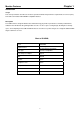
Electrical Requirements of G195HQ Standard Test Conditions All tests shall be performed under the following conditions, unless otherwise specified. Warm up time > 30 min. AC supply voltage 220V± 5%, 50± 3 Hz Ambient temperature 20°C ± 5°C Humidity 50% ± 10% Display mode 1366 x 768, 60 Hz, all white e-color mode Set to “User” mode Contrast control Set to The value under user mode, which allows that the brightest two of 32 linear distributed gray-scales (0 ~ 700mv) can be distinguished.
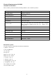
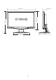
LCD Monitor General Specification LCD Panel Input Driving system TFT Color LCD Pixel pitch 0.3(H) x 0.3(V) Contrast Ratio 1000 : 1 (typ) Response time 5ms(Typ.). 8ms(max) Luminance of White 250 cd/m2(Typ.) Separate Sync. H/V TTL H-Frequency 30kHz – 80kHz V-Frequency 55-75Hz Viewing angle H:170°/ V:160° ( type)(CR>10) Display Colors 16.7M Weight(with stand) 3.7KG Weight(without stand) 3.36KG Dimension(with stand) 452.59(H)x 348.90(V) x 173.80(D) (mm) Dimension(without stand) 452.
60.00 mm G195HQ 288.95 mm 348.90 mm 452.59 mm 173.80 mm 261.
LCD Panel Specification of G195HQ This specification applies to the 18.5 inch-wide Color a-Si TFT-LCD Module M185XW01.The display supports the WXGA - 1366(H) x 768(V) screen format and 16.7M colors (RGB 6-bits +Hi-FRC data). All input signals are 1-channel LVDS interface and this module doesn’t contain an inverter board for backlight.
Optical Specifications 12
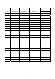
Factory Preset Timing of G195HQ 13
Monitor Block Diagram The LCD MONITOR will contain a main board, a power board, and a key board which house the flat panel control logic, brightness control logic and DDC. The power board will provide AC to DC Inverter voltage to drive the backlight of panel and the main board chips each voltage. Flat Panel and CCFL backlight CCFL Drive.
Main Board Diagram T89AM6D8MXAFH2 (Dual-Input Model) Crystal 14.31818MHZ (X401) Flash Memory EN25F20 (U402) Panel Interface (CN301) Scalar IC TSUMU5PEHL-LF Key control Interface (Include MCU, ADC, OSD) (CN402) (U401) H sync V sync RGB D-Data D-Clock D-Sub Connector (CN101) DVI Connector (CN102) T89AM5D8MXAFN2 Crystal 14.
Power Board Diagram 14.5V AC input Bridge Rectifier and Filter EMI filter Rectifier diodes Transformer 5V Start Resistor (R908) PWM Control (U901) Power Switch (Q901) Feedback Circuit Photo coupler (U902) Output Circuit Transformer (T801) MOSFET (Q803) 14.
Software Flow Chart 1 Y 2 3 N N 4 N 5 Y 6 N 7 8 Y Y 9 N 10 11 Y N N 12 13 Y Y N 14 15 Y 17 N 18 19 Y 17 16
Remark: 1) MCU initializes. 2) Is the EEPROM blank? 3) Program the EEPROM by default values. 4) Get the PWM value of brightness from EEPROM. 5) Is the power key pressed? 6) Clear all global flags. 7) Are the AUTO and SELECT keys pressed? 8) Enter factory mode. 9) Save the power key status into EEPROM. Turn on the LED and set it to green color. Scalar initializes. 10) In standby mode? 11) Update the lifetime of back light.
Main Board Layout 715G2883 Symbol 1 6 Description Symbol Description U401 TSUM1PEL PQFP-100 TSUMU5PEHL-LF PQFP-100(Dual-Input Model) CN302 WAFER U701 AP1117E33L-13 CN701 CONNECTOR 9P 2.0 U106 AZC099-04S SOT23-6L CN402 CONN 6PIN 2.0 U103 AZC099-04S SOT23-6L CN101 D-SUB 15PIN VERTICAL CONN WITH SCREW U402 EN25F20-100GCP 2Mb SOP-8 CN102 DVI 24PIN CONN F ATTACHED SCREW(Dual-Input Model) U104 AZC099-04S SOT23-6L U105 AZC099-04S SOT23-6L(Dual-Input Model) X401 14.
Installation To install the monitor to your host system, please follow the steps as given below: Steps 1. 1-1 Connect Video Cable a. Make sure both the monitor and computer are powered-OFF. b. Connect the VGA video cable to the computer. 1-2 Digital Cable (Only Dual-Input Model) a. Make sure both the monitor and computer are powered-OFF. b. Connect one end of the 24-pin DVI cable to the back of the monitor and connect the other end to the computer’s port.
Attaching / Removing the Base Attaching: Align the base with the stand and push the base towards the top of the monitor. Removing: Depress the release hooks as indicated first before removing the base and follow the arrow direction to remove it. Screen Position Adjustment To optimize the viewing position, you can adjust the monitor tilt by using both of your hands to hold the edges of the monitor as shown below. The monitor can be adjusted to 15 degrees up or 5 degrees down.
Chapter 2 Operating Instructions Press the power button to turn the monitor on or off. The other control buttons are located at front panel of the monitor. By changing these settings, the picture can be adjusted to your personal preferences. • The power cord should be connected. • Connect the video cable from the monitor to the video card. • Press the power button to turn on the monitor position. The power indicator will light up. User Controls Power Switch / Power LED: To turn the monitor ON or OFF.
eColor Management (OSD) Operation instructions Step 1: Press “ ”Key to open the Acer eColor Management OSD and access the scenario modes Step 2: Press “ ” or “ ” to select the mode Step 3: Press “ AUTO “ Key to confirm the mode and exit the eColor menu. Features and Benefits Adjusting the OSD settings The OSD can be used for adjusting the settings of your LCD Monitor.Press the MENU key to open the OSD. You can use the OSD to adjust the picture quality, OSD position and general settings.
1 Press the MENU key to bring up the OSD. 2 Using the 3 Use the keys, select Picture from the OSD. Then navigate to the picture element you wish to adjust. / keys to adjust the sliding scales. 4 The Picture menu can be used to adjust the current Brightness, Contrast,Colour Temp, Auto Config and other image-related qualities. Adjusting the OSD position 1 Press the MENU key to bring up the OSD. 2 Using the directional keys, select OSD from the on screen display.
Product information 1 Press the MENU key to bring up the OSD. 2 Using the keys, select Information from the OSD. Then the basic information of LCD monitor will show up for current input.
How to Optimize The DOS-Mode Plug And Play Plug & Play DDC2B Feature This monitor is equipped with VESA DDC2B capabilities according to the VESA DDC STANDARD. It allows the monitor to inform the host system of its identity and, depending on the level of DDC used, communicate additional information about its display capabilities. The DDC2B is a bi-directional data channel based on the I²C protocol. The host can request EDID information over the DDC2B channel.
Chapter 3 Machine Disassembly This chapter contains step-by-step procedures on how to disassemble the monitorG195HQ for maintenance. The tool for disassembly is as follows: Screwdriver, Hexagonal screwdriver, Putty knife. Disassembly Procedure 1.Lay the monitor on a flat, soft and clean surface. 2.Press the button remarked in green the remove the base. 3. Remove the two piece of cover hinge and the four screws remarked in red to remove the hinge assembly.
4.Remove the rear cover. Pry the monitor up then find out the hooks’ position, use the tool (like the picture or other card) to insert into the gap of bezel and rear cover.
Turn over the monitor and take off the rear cover. 4. Remove the bezel. Disconnect the connector remarked in green. PS: be careful to Disconnect the Key board connector, because the keyboard connector maybe damage.
Remove the 2 screws remarked in red. Remove the lamp connectors to remove the panel. Put attention to the LVDS cable.
6. Turn over the main frame and remove the four screws remarked in red and disconnected remarked in green to remove the main board and power board. Power board Main board Remove the speakers.
7.
Chapter 4 Troubleshooting This chapter provides troubleshooting information for the G195HQ: 1.Main Board 1) No Power No power Press power key and look if the picture is normal NG Please reinsert and make sure the AC of 100-240 is normal NG OK Reinsert or check the power section Measure U701 Pin2=3.3V, C704 (+) =1.
2) No Picture (LED is orange) No picture NG The button if under control X401 oscillate waveform is normal NG Replace X401 OK OK Check reset circuit of U401 is normal Measure U701 Pin2=3.3V, C704(+)=1.
3) Panel Power Circuit White screen Measure Q302 base is low level? NG X401 oscillate waveform is normal OK OK Check CN301 is solder and Q302, Q301 is OK? Check Correspondent component. NG Replace X401 Check reset circuit of U401 is normal NG NG OK OK Replace U401 Replace PANEL 35 Check Correspondent component.
2.
3.
2.) No Backlight Check C811(+)=14.5V NG Check adapter or MB OK Check ON/OFF signal NG Check Interface board OK Check U801 PIN11,14 have the output of square wave at short time NG Change U801 OK Check Q803 PIN5, 6, 7, 8 have the output of square wave at short time.
Chapter 5 Connector Information D-sub connect and DVI connect: 15-Pin Color Display Signal Cable 24-Pin Color Display Signal Cable (Dual-Input Model) 39
Chapter 6 FRU (Field Replaceable Unit) List This chapter gives you the FRU (Field Replaceable Unit) listing in global configurations of G195HQ. Refer to this chapter whenever ordering for parts to repair or for RMA (Return Merchandise Authorization). NOTE: Please note WHEN ORDERING FRU PARTS, that you should check the most up-to-date information available on your regional web or channel (http://aicsl.acer.com.tw/spl/).
Item Description TPV Part No. Acer Part No. Q`ty 1 BEZEL L185WA-9acer5 A34G1522AEMA1B0130 60.LJM0B.001 1 2 KEY BUTTON A33G0779AEM 1L0100 N/A 1 3 POWER BUTTON A33G0780AEM 1L0100 N/A 1 4 LENS A33G0768 1 1C0100 A15G0933101401 N/A 1 5 MAINFRAME 6 REAR COVER L205WA-9ACER5-S5 A15G0933101301 (Dual-Input Model) A34G1523AEM 4B0100 60.LJM0B.008 1 60.LJM0B.009 (Dual-Input Model) 60.LJM0B.
Part List Above picture show the description of the following component. Picture Description TPV Part No. A15G0933101401 Main_frame Acer Part No. 60.LJM0B.008 60.LJM0B.009 A15G0933101301 (Dual-Input (Dual-Input Model) Model) Bezel A34G1522AEMA1B0130 60.LJM0B.001 Panel 750GLU185X1414N000 LK.18005.016 A34G1523AEM 4B0100 60.LJM0B.002 Rear Cover Power Board 42 60.LJM0B.003 A34G1523AEM 3B0100 (Dual-Input (Dual-Input Model) Model) PWPC9821AQMY 55.LJM0B.
756GQ9CB BA256 00 Main Board 756GQ9CB BA255 55.LJM0B.001 00 (Dual-Input Model) 55.LJM0B.002 (Dual-Input Model) Key Board KEPC9QKO 55.LJO0B.002 Hinge A37G0137 1 60.LJM0B.004 Base A34G1521AEM 1B0100 Bracket Base A15G0932101 LVDS ASS'Y 095G8018 3XH60 43 60.LJM0B.007 N/A 50.LEF0B.
D-SUB Cable 089G 728CAA DB 50.LAL0B.002 089G1748HAA AC 50.LAN0B.003 089G404A18N CX 50.LBT0B.
Chapter 7 Schematic Diagram Main Board T89AM6D8MXAFH2 (Dual-Input Model) FB102 VGA_B+ MVCC_1 1 2 R105 R106 2K2 1/16W 5% R107 C103 C104 2K2 1/16W 5% 22pF 22pF DSUB_5V DDC1_SCL DDC1_SCL 14 13 R113 DDC1_SDA DSUB_SDA 12 100R 1/16W 5% 17 11 DSUB_B+ 2 100R 1/16WC106 5% 0.047uF DSUB_B- 2 75R 1/16W 5% R109 ESD_VCC R110 470R 1/16W 5% C107 1000pF DSUB_SOG 2 R111 100R 1/16W 5% C108 0.047uF DSUB_G+ 2 R114 100R 1/16W 5% C110 0.047uF DSUB_G- 2 R115 100R 1/16W 5%C111 0.
CN301 2 PA[0..9] PA[0..9] PA0 PA1 PA2 PA3 PA4 PA5 PA6 PA7 PA8 PA9 2 PB[0..9] LVA3P LVA3M LVACKP LVACKM LVA2P LVA2M LVA1P LVA1M LVA0P LVA0M CN302 LVA0M LVA1M LVA2M LVACKM LVA3M PB[0..
CMVCC VCC1.8 C710 0.1uF 16V FB702 300 OHM CN701 VCC3.3 C705 1 2 3 4 5 6 7 8 9 SM340A D701 + C704 0.1uF/16V MVCC 100uF25V Q702 KN2907AS CMVCC CMVCC BKLT-VBRI BKLT-EN PANEL_ID# Volume# Mute R705 R709 NC R710 NC Volume# 2 FB704 10K 1/16W 5% PANEL_ID# 2 Q703 KN2907AS Mute 2 R706 BKLT-VBRI adj_BACKLIGHT 2 VCC3.3 NC CONN lock type C713 NC 1K 1/16W 5% C701 0.1uF/16V R708 NC/2.2 OHM 2W C712 NC R701 0R05 1/4W DGND 1,2,3 VCTRL VCC3.3 1 2 DVI_5V DSUB_5V VCC3.
VCC1.8 VDDP 4 VCC3.3 AVDD VCC3.3 FB402 300OHM C412 VPLL 300OHM C409 + C403 C402 10uF/50V C404 C410 C411 0.
T89AM5D8MXAFN2 FB102 VGA_B+ 1 2 R105 BEAD R108 100R 1/16W 5% C102 0.047uF DSUB_B+ 2 100R 1/16WC106 5% 0.047uF DSUB_B- 2 C105 5pF/50V 75R 1/16W 5% VGA_B- R109 R110 470R 1/16W 5% C107 1000pF DSUB_SOG 2 R111 100R 1/16W 5% C108 0.047uF DSUB_G+ 2 R114 100R 1/16W 5% C110 0.047uF DSUB_G- 2 R115 100R 1/16W 5%C111 0.
CN301 2 PA[0..9] PA[0..9] PA0 PA1 PA2 PA3 PA4 PA5 PA6 PA7 PA8 PA9 2 PB[0..9] LVA3P LVA3M LVACKP LVACKM LVA2P LVA2M LVA1P LVA1M LVA0P LVA0M RXO0RXO0+ RXO1RXO1+ RXO2RXO2+ LVBCKM LVBCKP LVB3M LVB3P LVA0M LVA0P RXOCRXOC+ RXO3RXO3+ RXE0RXE0+ LVA1M LVA1P RXE1RXE1+ LVA2M LVA2P LVACKM LVACKP LVA3M LVA3P RXE2RXE2+ RXECRXEC+ RXE3RXE3+ 30 29 28 27 26 25 24 23 22 21 20 19 18 17 16 15 14 13 12 11 10 9 8 7 6 5 4 3 2 1 CN302 LVA0M LVA1M LVA2M LVACKM LVA3M 13 11 9 7 5 3 1 RXE0RXE1RXE2RXECRXE3- PB[0..
CMVCC VCC1.8 C710 0.1uF 16V FB702 300 OHM CN701 VCC3.3 C705 SM340A D701 1 2 3 4 5 6 7 8 9 CMVCC CMVCC BKLT-VBRI BKLT-EN PANEL_ID# Volume# Mute MVCC + C704 0.1uF/16V 100uF25V Q702 KN2907AS Volume# R705 R709 NC R710 NC 2 FB704 10K 1/16W 5% PANEL_ID# 2 Q703 KN2907AS Mute 2 R706 BKLT-VBRI adj_BACKLIGHT 2 VCC3.3 NC CONN C713 NC lock type 1K 1/16W 5% C701 0.1uF/16V R708 NC/2.2 OHM 2W C712 NC R701 0R05 1/4W DGND 1,2,3 VCTRL VCC3.3 1 2 DVI_5V DSUB_5V VCC3.
VCC1.8 VDDP 4 0 OHM +-5% 1/8W AVDD VCC3.
Power board ! 1 R929 100 OHM 1/4W C916 R930 100 OHM 1/4W 0.001uF F801 0R05 1/4W 5% +14.5V 2 + BD901 KBP208G 3 R903 100 OHM 1/4W + ZD901 MTZJ T-72 16B R904 220 OHM 2W C918 1000UF25V R905 470R 1/10W 5% 4 - D901 NC/SR5150 1 2 1 2 R906 100KOHM +-5% 2WS ! R931 NC C937 ! + R932 NC ! 3 L901 4 + R910 100 OHM 1/4W 1 R923 220 OHM 1/4W D906 3 R920 1K 1/10W 1% U902 PC123X2YFZOF 2 C914 470pF 1 R918 10K 1/10W 1% FB901 BEAD NR901 NTCR C922 470uF 16V R919 150R 1/8W 5% C912 0.
REF +14.5V + C811 470uF 25V R805 10K 1/10W 5% CN801 C814 1uF 25V 0.1uF50V R803 1 2 R816 C801 5pF6KV 10 OHM +-5% 1/10W RJ805 R811 6 T801 7 POWER X'FMR LI1 CONN 2K 1/10W 5% R807 OV2 C815 DIM R815 10K 1/10W 5% C809 0.001uF C802 0.0022uF/50V 10K 1/10W 5% 0R05 1/4W 5% C813 10 OHM +-5% 1/10W 3 4 R801 412 OHM 1/10W D803 2 ON/OFF 2N2 50V AM9000ES 0.
Key board ZD007 2 NC/UDZSNP5.6B 1 LED001 4 3 LED 2 1 2 NC/UDZSNP5.6B CN001 LBADC1 LBADC2 DC_POWERON LED_GRN# LED_RED# C004 0.1uF 50V R004 R005 C005 NC 2Kohm 1/10W +/-1% 1K 1/10W 1% VOL- ECOLOR C002 C003 NC 0.1uF 50V AUTO C001 NC 8 2Kohm 1/10W +/-1% VOL+ CONN R002 LED_GRN# LED_RED# POWER 1 2 3 4 5 6 MENU 7 ZD008 1 LBADC2 VOL+(2K) 1.1V AUTO(1K) 0.65V ECOLOR(GND) 0 V 4 3 5 4 CN001 CONNECTOR LED POWER ECOLOR AUTO MENU VOL- VOL+ TPV Victory Electronics Co .