User's Manual
Manuals
Brands
Acer Manuals
Computers
G510
61
62
63
64
65
66
67
68
69
70
Table Of Contents
Notices
FCC notice
Laser compliance statement
Important safety instructions
1 System tour
Features summary
External and internal structure
Front bezel
Front panel
Rear panel
Internal components
System boards
Mainboard layout
Hot Plug HDD Cage backplane board layout
2 System setup
Setting up the system
Preinstallation requirements
Connecting peripherals
To connect the PS/2 keyboard
To connect the PS/2 mouse
To connect the VGA monitor
To connect a printer
To connect the power cable
Turning on the system
Power-on problems
Operating system configuration
Network connection
Tower-to-rack option
Turning off the system
3 Upgrading the system
Upgrading the system
Installation precautions
Opening the server
Before opening the server
To open the front bezel
To remove the front bezel
To remove the inner (front) panel
To remove the side panel
Configuring the Hot Plug HDD cage
To remove the Hot Plug HDD cage
To install a hard disk into the Hot Plug HDD cage hard disk carrier
To install the Hot Plug HDD cage
Configuring the non-Hot Plug HDD cable cage
To remove the HDD cable cage
To install a hard disk into the HDD cable cage
To install the SCSI cable cage
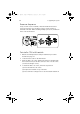
Installing and removing storage devices
To replace the 3.5-inch floppy drive
To install a 5.25-inch storage device
Upgrading the CPU
To remove a CPU with heatsink
Processor Sequence
To install a CPU with heatsink
Upgrading the system memory
To remove a DIMM
To install a DIMM
Installing an expansion card
To install an expansion card
Installing a redundant power supply module
To install a redundant power supply module
4 BIOS setup
BIOS setup
Entering BIOS setup
Main
Advanced
Super I/O Configuration
IDE Configuration
Floppy Configuration
PCI/PnP Configuration
Boot Settings Configuration
Event Log Configuration
Onboard Devices Configuration
Power
Boot
Boot Device Priority
Hard Disk Drives
Removable Devices
ATAPI CD-ROM Devices
Security
To set a Supervisor/User password
To change the Supervisor/User password
To remove the User password
Exit
Appendix A: ASM Quick Installation Guide
Installing ASM
System requirements
System setup
Appendix B: Altos G510 Rack Installation Guide
System rack installation
Screw types for rack installation
Installing the system into the rack
Index
53
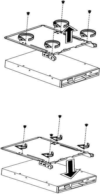
4
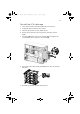
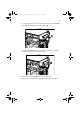
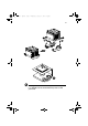
Remove the four screws that hold the old drive to the drive carrier
then pull it out.
5
Install a new 3.5-inch drive in the drive carrier then secure it with
the four screws you removed in the previous step.
BB!H621!.!FO/cppl!!Qbhf!64!!Xfeoftebz-!Kbovbsz!9-!3114!!21;63!BN
1
...
...
61
62
63
64
65
...
...
134