PC/II+p Socket 7 Class Embedded Modular Computer for Low-Power Applications Technical Reference Manual Please obtain copies of the Supplement and Addendum documents for PCpi specific information. Supplement document gives an overview of changes that occur when migrating to the megatel PCPi platform. The Addendum provides technical details of options or features on the PCpi that were not offered on the PC/II+p. Document Number: MT002615 Revision: 1.
TERMS OF USE FOR THIS MANUAL Those portions of this Manual (including this part) containing Notices of Copyright, Warranty, Intellectual Property, Trademark Information and legal cautions may not be altered, concealed or deleted by anyone without the explicit consent of Megatel in writing.
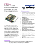
PC/II+p Socket 7 Class Embedded Modular Computer for LowPower Applications The PC/II+p board is a rugged full featured PENTIUM or K6 SBC that has been engineered with available leading edge components and software. This board supports the available lowpower socket 7 processors, and utilizes the ALI chipset which provides both PCI and ISA buses. It is PC/104 compliant and 104Family I/O compliant.
PC/II+p Board Technical Reference Manual 4 Revision List Page REVISION MT002605 2000/02/02 Prerelease Version for PC/II+p v2.00 Manual reformatted Component Top, Bottom & Dimension Diagrams updated Component naming updated Video Resolution, Colors, Refresh & Clocks Support updated 1ff 30, 31, 96 Various n/a REVISION MT002606 2000/04/25 Prerelease Version for PC/II+p v2.01 NOTE: As of PCB Version 2.
PC/II+p Board Technical Reference Manual 5 REVISION MT002613 2001/01/28 Release Version for PC/II+p v2.03 NOTE: This revision of PCB Version 2.03 provides full support for the Intel Embedded Low Power 266 MHz processor. Notice of new document MT004702, "Ethernet Appbook" added to Ethernet Section Interrupt IRQ Map updated DMA Channel MAP updated Clarification on the use of the RSTSW# I/O Pin (Manual Reset Switch) Added 38 81 82 64,24 REVISION MT002614 2001/03/15 Release Version for PC/II+p v2.
PC/II+p Board Technical Reference Manual Table of Contents 6 Page 1 INTRODUCTION................................................................................................................................12 1.1 PC/II+p Overview ........................................................................................................................12 2 REFERENCE DOCUMENTS.............................................................................................................14 2.1 Datasheets .......
PC/II+p Board Technical Reference Manual 7 7.16 North Bridge ..............................................................................................................................52 7.17 Parallel Port ...............................................................................................................................52 7.17.1 Parallel Port Pinout .............................................................................................................53 7.18 PC/104 Bus Interface .....
PC/II+p Board Technical Reference Manual 8 11.3.1 Option a – Watchdog ..........................................................................................................90 11.3.2 Option b – Power Supply Arrangement ..............................................................................90 11.3.3 Option c – Panel ENAVEE Polarity.....................................................................................91 11.3.4 Option E – Ethernet .....................................................
PC/II+p Board Technical Reference Manual List of Figures Figure 1 Figure 2 Figure 3 Figure 4 Figure 5 Figure 6 Figure 7 Figure 8 Figure 9 9 Page PC/II+p Block Diagram (V2.04) .............................................................................................20 Component Placement – Top Side (v2.04) ...........................................................................30 Component Placement – Bottom Side (v2.04) ......................................................................
PC/II+p Board Technical Reference Manual Table 42 Table 43 Table 44 Table 45 Table 46 Table 47 Table 48 10 Memory Map – First Megabyte .............................................................................................80 Interrupt Map.........................................................................................................................81 DMA Map ..............................................................................................................................
PC/II+p Board Technical Reference Manual 11 Preface This document uses hyperlinks to assist you in navigating. In this document, hyperlink text is underlined - but color is normally black. Underlining is not used elsewhere. In some cases where, within a table, hyperlink text is also colored, the hyperlink text will not be black in that case but, instead, reflect the color normally used in the table for the corresponding item.
PC/II+p Board Technical Reference Manual 12 1 Introduction Thank you for your interest in the Megatel PC/II+p Cpu board, one of the 104Family of scalable complete computer boards from Megatel. If you have chosen this board for your applications, you have chosen a rugged, reliable high-performance and low-cost solution. This board has been engineered to be compatible not only with other boards in the Megatel 104Family line, but also to the PC/104 industry standard for embedded computer-based products.
PC/II+p Board Technical Reference Manual 13 All peripheral I/O, including Video CRT, 24-Bit Flat Panel, Keyboard, Mouse, IDE, 2 Serial and Parallel ports are pulled to a Mass I/O Connector on the board. The Ethernet is provided separately on a standard 2x5 pin header. A 12-pin power header is provided to supply the single +5V rail to the board and the +5V rail is regulated to +3.3V, +2.5V and the CPU Core Voltage (+1.
PC/II+p Board Technical Reference Manual 14 2 Reference Documents 2.1 Datasheets Acer Laboratories Inc. Aladdin IV – M1531B Cpu-to-PCI bridge, Memory, Cache and Buffer Controller Data Sheet, Version 1.2, Jan 1998 Acer Laboratories Inc. Aladdin – M1543 Desktop South Bridge Datasheet, Version 1.25, Jan 1998 AMD AMD-K6-2E Embedded Processor Datasheet, Advanced Micro Devices, Pub# 22529, Revision B/0, January/2000.
PC/II+p Board Technical Reference Manual 15 3 Specification Summary 3.1 PC/II+p Board Specifications Board Form Factor: Board Type: 3.775 x 3.550 inch, PC/104 compliant FR4 Architecture: PC®/AT Central Processing Unit: CPGA 321-Pin Socket, for Low-Power "Socket 7" or Compatible Processor Accepts 321-Pin CPGA Processors or 296-Pin SPGA Low-Power Processors (from Intel or AMD – see below for supported processors) Full Socket 7 Compliance.
PC/II+p Board Technical Reference Manual 16 PC Speaker Output: Available on Mass I/O connector Memory Bus: Address Bus: 64-Bit Data bus 32-Bit Address bus Power Monitoring: Dual 5% monitor – 5V rail and on-board 3.
PC/II+p Board Technical Reference Manual 17 Video CRT & Flat Panel: Intel 69030 HiQVideo Accelerator VGA register set compatibility and I/O accessibility Includes On-Chip SDRAM 4 MB of high-speed SDRAM for video buffer Memory SDRAM operation at 83 MHz Memory SDRAM transfers up to 664 MBytes/sec Supports Analog CRT RGB Video Interface Supports 24-Bit Flat Panel Interface Flexible Panel Interface – TFT/MIM, DSTN, SSTN, EL, Plasma Supports Mono and Color Supports VGA, SVGA, XGA, SXGA, UXGA resolutions Suppo
PC/II+p Board Technical Reference Manual 18 Daylight savings time support Unique 48-Bit Serial Number can be used for customer application Watchdog: Dallas DS1706 with Watchdog Hardware timer is strobed once per second or faster Hardware timer expiry issues system RESET Hardware disable function via jumper Software BIOS Disable, enable and strobe functions USB Integrated controller supports one root hub with two USB ports Supports OpenHCI 1.
PC/II+p Board Technical Reference Manual 19 Speaker Output – 1 USB port A – 2 USB port B – 2 Video Analog (CRT) – 5 Video Panel Interface (24-bit) – 32 Power & Ground Supply Voltage: Supply Power Rating: Supply Regulation: +5V Max Rise Time: Single supply at +5V 5% +5V Supply requires regulation to within 5% (+3V to +5V) required within 100 ms Storage Temperature: Operating Temperature: -50C to +125C, battery excluded Commerical 0C to +70C standard Industrial -20C to +85C : please call megatel for avai
PC/II+p Board Technical Reference Manual 20 3.2 PC/II+p Board Block Diagram For a description of component reference identifiers in the diagram, see section 6.1.
PC/II+p Board Technical Reference Manual 21 4 Settings 4.1 Jumper Settings – Cpu Type and Clock Frequencies Refer to Section 6.2 for the Component Placement – Top Side diagram. All jumpers are normally on the TOP side of the board. This table applies only to jumpers J003, J004, J005, and J006. These jumpers are populated as required by the processor option that you select.
PC/II+p Board Technical Reference Manual 22 4.2 Jumper Settings – Other Refer to Section 6.2 for placement of Jumpers. All jumpers are normally on the TOP side of the board.
PC/II+p Board Technical Reference Manual 23 5 Electrical Specifications The PC/II+p operates on a single +5V ± 5% supply. Power is supplied to the board through J907, the +5V Power Connector. On-board power requirements at +3.3V, +2.5V and VCPUCORE are generated on-board, using regulators (dual switching supplies provide +3.3V and VCPUCORE voltages). The board contains a split power plane, two dedicated power planes, and a dedicated ground plane.
PC/II+p Board Technical Reference Manual 24 5.2 Recommended Operating Conditions Table 4 Electrical – Recommended Operating Conditions Parameter Power Supply Power Supply Rise Time Operating Ambient Temperature Digital Symbol Min Typical Max Units VCC 4.75 5.0 5.25 V 100 ms +70 °C (1) +125 °C (2) +3.0V to +5.0V SVCC (Power Applied) TA 0 TS -55 Storage Ambient Temperature 20.0 Humidity (Untested) HA 10 90 % RH MR-RSTSW# Input Level Low Level RSTSWL -0.03 +0.
PC/II+p Board Technical Reference Manual 25 5.3 DC Characteristics Table 5 Electrical – DC Characteristics Parameter Power Supply Power Supply Current Symbol Min Typical Max Units (digital) VCC 4.75 5.0 5.25 V +5V Supply ICC5 Power PDD5 1.1A NOTES A (1),(2) W (1) Over Recommended Operating Conditions NOTES (1) Power requirements will vary depending upon the Cpu speed, amount of main memory and other options chosen.
PC/II+p Board Technical Reference Manual 26 5.4 Voltage Monitor A MicroMonitor is included on the board, the Dallas Semiconductor DS1706S, to provide both a watchdog function and a dual-voltage monitor function. This section discusses the voltage monitor function; refer to section 7.29 for a description of the watchdog function. +3.3V Monitor The +3.3V power supply is monitored by the DS1706S. When the +3.3V power supply falls below the minimum Vcc tolerance (2.85v to 3.
PC/II+p Board Technical Reference Manual 27 5.5 PC/104 Bus Drive Current The PC/104 bus drive current is specified by the PC/104 Specification, Version 1.3, listed in section 2.2. The PC/II+p board complies to this standard. Most PC/104 bus signals have a reduced bus drive requirement of 4 mA. The 4 exceptions are open collector driven signals, which must drive 330-ohm pullup resistors defined by the P996 specification.
PC/II+p Board Technical Reference Manual 28 6 Component Summary 6.1 Bill of Materials The major components on the PC/II+p board are contained in the following table. See Notes. Table 8 Board Component List (v2.04) DESCRIPTION 1 PART 2 VENDOR TRANSFORMER – Isolation, Ethernet AUI ST7033 VALOR 1 TRANSFORMER – Isolation, Ethernet 10Base-T ST7010 VALOR J003,J004 J005,J006 4 JUMPER – 1x2 2mm, Cpu Type & Speed Select M22-2010802 HARWIN J008 1 HEADER – 1x2 .
PC/II+p Board Technical Reference Manual 29 DESCRIPTION 1 PART 2 VENDOR 1 FLASH ROM – BIOS, 2Mbit (256KB) Flash 29EE020 SST 1 SOCKET – FLASH DISK DIP 32 0 FLASH DISK MODULE – 12 MB (USER SUPPLIED) MD2200-12MB M-SYSTEMS 0 FLASH DISK MODULE – 24 MB (USER SUPPLIED) MD2200-24MB M-SYSTEMS 0 FLASH DISK MODULE – 72 MB (USER SUPPLIED) MD2200-72MB M-SYSTEMS 0 FLASH DISK MODULE – 144 MB (USER SUPPLIED) MD2200-144MB M-SYSTEMS U007 1 NORTH BRIDGE – HOST BUS TO PCI, & DRAM CONTROLLER M1531
PC/II+p Board Technical Reference Manual 30 6.2 Component Placement – Top Side The following diagram shows the components on the top (component) side of the PC/II+p board. J003 J004 J005 J006 L002 U022 1763 J904 U023 1644 U020 69030 Y001 14.318 MHZ U002 SOCKET-7 AMD / INTEL CPU BAT1 3V U007 M1531B J908 U008 M1543 Y004 32K U021 7558 Y002 Y003 32K L001 20M D001 F002 ST7010 F001 ST7033 J010 J009 J903 J019 J901 J902 J905 J907 Figure 2 Component Placement – Top Side (v2.
PC/II+p Board Technical Reference Manual 31 6.3 Component Placement – Bottom Side The following diagram shows the components on the bottom (solder) side of the PC/II+p board. U012 U013 U011 48LCxM16 48LCxM16 1 U010 48LCxM16 1 48LCxM16 1 1 1 U005 4829EE020 U001 U017 ADM211E 1 1 U006 FLASH DISK 1 1 U018 ADM211E U014 DS1706 1 1 U003 93C46 U004 CS8900 U019 DS1685 1 1 1 U024 Figure 3 Component Placement – Bottom Side (v2.
PC/II+p Board Technical Reference Manual 32 7 Functional Specifications 7.1 Bridge See Bus, DRAM Memory, Peripheral Controllers, Section 7.2. 7.2 Bus, DRAM Memory, Peripheral Controllers The PC/II+p board utilizes the ALI Aladdin M1531B north bridge controller for Socket 7 CPUs, and the ALI Aladdin M1543C-B1 south bridge controller, to generate the PCI and ISA buses respectively. The north bridge provides bridging between the 66 MHz Pentium-class host bus (FSB) and the 33 MHz PCI bus.
PC/II+p Board Technical Reference Manual 33 7.4 Connectors, Headers and Sockets Connectors, Headers and Sockets sample part numbers are given in this section, and pinout information can be viewed from this section by using the links provided in the table below. All connectors and headers are through-hole type and are normally mounted on the TOP (component) side of the board. Headers can be top or bottom mounted.
PC/II+p Board Technical Reference Manual 34 7.4.1 Connector Sample Part Numbers The following connectors are available (by option, except for J907 which is required): • • • • J901,J902 – PC/104 Connectors AB and CD – 2 x 32 and 2 x 20 Header (.100 inch) J903,J904 – Mass I/O Connector – 5 x 11, 5 x 22 or 5 x 33 HM 2-mm connector J905 – Ethernet Connector – 2 x 5 Header (.100 inch) J907 – Power Connector (+5V) – 1 x 12 Header (.
PC/II+p Board Technical Reference Manual 35 7.4.2 AMP Connector (Right-Angle Receptacle) Dimensions The following diagram and picture is representative of the AMP Z-PACK 5X11 (TYPE C) connector, one of the connectors used on the PC/II+p Mass I/O Interface, and were provided by AMP. Please refer to the AMP Z-PACK HM 2MM catalog for more information.
PC/II+p Board Technical Reference Manual 36 7.5 Cpu Processor PC/II+p contains a 321-Pin socket for a Socket 7 Processor. Socket 7 specification is backward compatible with Socket 5 and with many 296-Pin SPGA and CPGA processors. Bus speeds up to 66 MHz are supported by the Socket 7.
PC/II+p Board Technical Reference Manual 37 7.6 Disk See Flash Disk, section 7.10. See Floppy Disk Interface, section 7.11. See IDE / ATA Ultra 33 Interface, section 7.12.
PC/II+p Board Technical Reference Manual 38 7.7 Ethernet Interface PC/II+p contains an optional, highly-integrated LAN Ethernet Interface, that is used in networking applications. This option includes the single-chip Crystal CS8900 controller (U004), a configuration EEPROM (U003), isolation transformers for either 10Base-T (F002) and/or AUI (F001), depending upon the option ordered, a dual LED (D001) for link and local activity, and an on-board Ethernet header (J905).
PC/II+p Board Technical Reference Manual 39 7.7.1 Ethernet Interface Pinout Figure 4 Diagram – J905 – Ethernet 2x5 Pin .100 Inch R/A Male Header 2 4 6 8 10 ⊕ ⊕ 1 ⊕ ⊕ 3 ⊕ ⊕ 5 ⊕ ⊕ 7 ⊕ ⊕ 9 NOTES 1 Top (component) view is shown. Table 11 Pinout – J905 – Ethernet 2x5 Pin .
PC/II+p Board Technical Reference Manual 40 Table 12 Signals – J905 – Ethernet 10Base-T Interface PIN NAME E1-TD- PIN# 7 SIGNAL NAME Negative Transmit Data E1-TD+ 8 Positive Transmit Data E1-RD- 3 Negative Receive Data E1-RD+ 4 Positive Receive Data SIGNAL DESCRIPTION Negative Differential Manchester-encoded Transmit Data Line, 10 Mbps, from onboard 10 BASE T Isolation Transformer (1:SQRT(2)) Pin 11. Connect to external RJ45 connector Pin 2.
PC/II+p Board Technical Reference Manual 41 7.8 Fan Connector – J008 The FAN connector (J008) is a basic feature on PC/II+p boards and is always shipped. This connector supplies +5V and Ground pins which may be used to power a CPU-mounted fan. For PC/II+p systems containing a high performance version of the processor, a fan may be used for cooling purposes, depending upon the application. Lower speed processor configurations may not require a fan to be installed.
PC/II+p Board Technical Reference Manual 42 7.9 Flash ROM – BIOS The standard ROM on the PC/II+p is a 2 Mbit (256K Byte) flash EEPROM. This EEPROM contains the system BIOS and all option BIOS modules, including the SVGA BIOS and any other bios modules required to interface to on-board peripherals. All PC/II+p boards are shipped with a flash BIOS. BIOS code is shadowed in system memory located between C0000h and FFFFFh. The system BIOS code occupies the top segment of real mode memory (F0000h to FFFFFh).
PC/II+p Board Technical Reference Manual 43 7.10 Flash Disk PC/II+p contains a 32-Pin DIP socket (U006) that can be user-populated with a flash disk device. Megatel supports flash disk modules which are compatible with the Disk-on-Chip® product provided by MSystems. The Disk-on-Chip® product is available in sizes up to at least 144 MB. For more detailed information on Disk-on-Chip® products, please contact M-Systems.
PC/II+p Board Technical Reference Manual 44 7.11 Floppy Disk Interface PC/II+p contains an integrated 2.88 MB (formatted) Floppy Disk Drive Controller. The M1543-based controller interface signals are made available on the Mass I/O connector, J904. For signal definitions, refer to Table 17. The controller is software compatible with the industry-standard 82077SL and PD765A architecture and supports 16-byte data FIFOs. It contains a high-performance data separator. It supports 3 modes of 3.
PC/II+p Board Technical Reference Manual 45 7.11.1 Floppy Disk Interface Pinout Table 17 Signals – J904 – Floppy Disk Interface PIN NAME F1-DENSL0# PIN# e20 SIGNAL NAME Density Select SIGNAL DESCRIPTION This signal Indicates whether a low (250/300 Kb/s) or high (500/1000 Kb/s) data rate has been selected. F1-DIR# d21 Direction This active low output determines the direction of the head movement (low = step-in, high = step-out). During the write or read modes, this output is high.
PC/II+p Board Technical Reference Manual 46 7.12 IDE / ATA Ultra 33 Interface PC/II+p contains an integrated IDE/ATA Master controller. The IDE interface signals are provided on the Mass I/O Connector, J903 – refer to Table 18. The controller is capable of accelerated PIO data transfers as well as acting as a PCI bus master on behalf of an IDE DMA slave device.
PC/II+p Board Technical Reference Manual 47 7.12.1 IDE Interface Pinout Table 18 Signals – J903 – IDE/ATA Interface PIN NAME PIN# SIGNAL NAME SIGNAL DESCRIPTION A1-DA0 a6 Address Bus 0 This signal is Address Bit 0 of the ATA Address Bus that is connected to IDE Channel. A1-DA1 b6 Address Bus 1 This signal is Address Bit 1 of the ATA Address Bus that is connected to IDE Channel. A1-DA2 e7 Address Bus 2 This signal is Address Bit 2 of the ATA Address Bus that is connected to IDE Channel.
PC/II+p Board Technical Reference Manual 48 PIN NAME PIN# SIGNAL NAME SIGNAL DESCRIPTION 1-DIOR# b5 IO Read Command A1-DIOR#,A1-DDMARDY#,A1-HSTROBE DIOR# is the strobe signal asserted by the host to read device registers or the data port. HDMARDY# is a flow control signal for Ultra DMA data in bursts. This signal is asserted by the host to indicate to the device that the host is ready to receive Ultra DMA data in bursts. The host may negate HDMARDY# to pause an Ultra DMA data in burst.
PC/II+p Board Technical Reference Manual 49 PIN NAME PIN# SIGNAL NAME SIGNAL DESCRIPTION A1-IORDY a5 IDE Ready A1-INTRQ d6 IDE Interrupt A1-IORDY,A1-DDMARDY#,A1-DSTROBE A1-IORDY This signal is negated to extend the host transfer cycle of any host register access (Read or Write) when the device is not ready to respond to a data transfer request. If the device requires to extend the host transfer cycle time at PIO modes 3 and above, the device shall utilize A1-IORDY.
PC/II+p Board Technical Reference Manual 50 7.13 Keyboard & Mouse Interface PC/II+p contains an integrated PS2/AT-style keyboard and PS2-style Mouse controller. The 8042 compatible controller is supported by the Acer Laboratories M1543C south bridge and I/O controller. The keyboard and mouse interface signals are pulled to the Mass I/O Connector, J904. EMI suppression for both the keyboard and mouse clock and data lines is provided on-board.
PC/II+p Board Technical Reference Manual 51 7.14 Memory The PC/II+p board is shipped with soldered 66 MHz (10 ns) typical, 3.3v Synchronous DRAM memory, soldered to the bottom of the board. The amount of soldered on a given board is automatically detected by the BIOS; there are no memory jumpers to configure. DMA can directly access memory anywhere in the 32-bit physical address space.
PC/II+p Board Technical Reference Manual 52 7.16 North Bridge See Bus, DRAM Memory, Peripheral Controllers, Section 7.2. 7.17 Parallel Port PC/II+p provides an integrated Parallel Port controller. The parallel port interface signals are provided on the Mass I/O Connector, J904.
PC/II+p Board Technical Reference Manual 53 7.17.1 Parallel Port Pinout Table 22 Signals – J904 – Parallel LPT1 Interface PIN NAME P1-AFD# PIN# b9 SIGNAL NAME Autofeed Output SIGNAL DESCRIPTION This active low output causes the printer to automatically feed one line after each line is printed. This signal is the complement of bit 1 of the Printer Control Register. P1-AKN# e12 Acknowledge This active low output from the printer indicates it has received the data and is ready to accept new data.
PC/II+p Board Technical Reference Manual 54 7.18 PC/104 Bus Interface PC/II+p provides a 16-bit (or 8-bit) PC/104 bus through on-board connectors J901 and J902. One or more PC/104 option modules can be attached to PC/II+p via the PC/104 bus connectors. PC/II+p supports a 64-pin (2x32) PC/104 AB Bus connector (J901), and a 40-pin (2x20) PC/104 CD Bus connector (J902) — Refer to Figure 5 and Figure 6.
PC/II+p Board Technical Reference Manual 55 Table 24 PC/104 (ISA) Refresh Periods VALUE OF REG 43h BITS 5-4 ISA REFRESH PERIOD SETTING COMMENT 00 15 uSec Default 01 30 uSec 10 60 uSec 11 120 uSec Table 25 PC/104 (ISA) 16-Bit Memory Wait States VALUE OF REG 43h BITS 3-2 REFRESH PERIOD SETTING COMMENT 00 normal 16-bit access Default 01 insert 1 wait state 10 insert 2 wait states 11 insert 3 wait states Table 26 PC/104 (ISA) 16-Bit I/O Wait States VALUE OF REG 43h BITS 1-0 WAIT STATE
PC/II+p Board Technical Reference Manual 56 7.18.1 PC/104 Pinout Figure 5 Diagram – J901 – PC/104 (Rows A and B) – 2 X 32 .100" Header 1 2 3 4 5 6 7 8 9 10 11 12 13 14 15 16 17 18 19 20 21 22 23 24 25 26 27 28 29 30 31 32 ⊕ ⊕ ⊕ ⊕ ⊕ ⊕ ⊕ ⊕ ⊕ ⊕ ⊕ ⊕ ⊕ ⊕ ⊕ ⊕ ⊕ ⊕ ⊕ ⊕ ⊕ ⊕ ⊕ ⊕ ⊕ ⊕ ⊕ ⊕ ⊕ ⊕ ⊕ ⊕ B ⊕ ⊕ ⊕ ⊕ ⊕ ⊕ ⊕ ⊕ ⊕ ⊕ ⊕ ⊕ ⊕ ⊕ ⊕ ⊕ ⊕ ⊕ ⊕ ⊕ ⊕ ⊕ ⊕ ⊕ ⊕ ⊕ ⊕ ⊕ ⊕ ⊕ ⊕ ⊕ A NOTES (1) Top (component) view is shown. Figure 6 Diagram – J902 – PC/104 (Rows C and D) – 2 X 20 .
PC/II+p Board Technical Reference Manual PIN GROUP 1,3 COL 2 ROW A ROW B PC104 - AB 20 SA11 SYSCLK PC104 - AB 21 SA10 IRQ7 PC104 - AB 22 SA9 IRQ6 PC104 - AB 23 SA8 IRQ5 PC104 - AB 24 SA7 IRQ4 PC104 - AB 25 SA6 IRQ3 PC104 - AB 26 SA5 DACK2* PC104 - AB 27 SA4 TC PC104 - AB 28 SA3 BALE PC104 - AB 29 SA2 +5V PC104 - AB 30 SA1 OSC PC104 - AB 31 SA0 0V PC104 - AB 32 0V 0V 57 NOTES (1) Refer to the PC/104 Specification.
PC/II+p Board Technical Reference Manual 58 Table 28 Pinout – J902 – PC/104 (Rows C and D) – 2 X 20 .
PC/II+p Board Technical Reference Manual 59 7.19 Power (+5V) Connector - J907 The PC/II+p is shipped with J907 installed. J907 is a +5V Power Header that sources +5V from an external supply to the board. All other on-board power planes (such as +3.3V, +2.5V, +1.9V) are generated by onboard high-efficiency switching regulators. The +5V power connector, J907, is part of the basic board. 7.19.
PC/II+p Board Technical Reference Manual 60 7.21 Real-Time Clock The PC/II+p contains an optional Real-Time Clock (RTC), a Dallas Semiconductor DS1685E. This clock is a full-function part, and is certified as Year-2000 compliant by Dallas. The RTC uses a 32.768 KHz crystal and a 3.0V Lithium battery. The battery is soldered onto the circuit board. Information contained in the following sub-sections is presented in summary form.
PC/II+p Board Technical Reference Manual 61 7.21.4 Real-Time Clock – Interrupt 1Ah Functions The BIOS supports AT compatible real-time clock functions using software interrupt 1Ah. In addition, the PC/II+p BIOS supports the following functions using the software interrupt 1Ah, which provide read and write access to bank 0 and bank 1 SRAM memory in the real-time clock, and read access to the unique serial number encoded in the real-time clock chip. 1.
PC/II+p Board Technical Reference Manual 62 7.21.
PC/II+p Board Technical Reference Manual RTC Bank 0 Offset Description 4F RAM Byte 4F RTC Address - 3 50 RAM Byte 50 Extended RAM Address 51 RAM Byte 51 Reserved 52 RAM Byte 52 Reserved 53 RAM Byte 53 Extended RAM Data Port 54-7F RAM Bytes 54-7F Reserved 63 Bank 1 Access Description Access Table 31 RTC Extended RAM Memory Map Via 50 & 53 Bank 0 Bank 1 Extended RAM 00-7F - RAM Bytes 00-7F MT002615 RW ©1999-2001, Megatel Computer Corporation
PC/II+p Board Technical Reference Manual 64 7.22 Reset Switch PC/II+p responds to a "reset switch" signal input (MR-RSTSW#) from the Mass I/O Connector, J904. The reset switch signal is Active Low. It should be left unconnected if unused. See the column, "SIGNAL DESCRIPTION", in Table 32 below, for requirements. The on-board supervisor asserts System RESET for as long as MR-RSTSW# is held low, and for 130 to 200 ms after this signal is floated. An on-board pull-up of 40 KΩ is used.
PC/II+p Board Technical Reference Manual 65 7.23 Serial Ports PC/II+p basic board contains a standard RS-232 port; optionally, a second standard RS-232 port may be ordered. Each serial port includes a high performance 16C550 compatible UARTs (provided by the ALI M1543C), and contains an associated Analog ADM211E transceiver. RS-232 serial interface signals are provided on the Mass I/O Connector, J904.
PC/II+p Board Technical Reference Manual 66 For more detailed information about serial I/O, please refer to the Acer Laboratories M1543C datasheet, found in section 2, "Reference Documents" in this document. 7.23.1 Serial COM1 Pinout Table 34 Signals – J904 – Serial COM1 Interface PIN NAME PIN# SIGNAL NAME SIGNAL DESCRIPTION C1-CTS# a13 Clear to Send This active low input is the handshake signal which notifies the UART that the modem is ready to receive data.
PC/II+p Board Technical Reference Manual 67 7.23.2 Serial COM2 Pinout Table 35 Signals – J904 – Serial COM2 Interface PIN NAME PIN# SIGNAL NAME SIGNAL DESCRIPTION C2-CTS# c15 Clear to Send This active low input is the handshake signal which notifies the UART that the modem is ready to receive data. The CPU can monitor the status of C2-CTS# signal by reading bit 4 of Modem Status Register (MSR). A C2-CTS# signal state change from low to high after the last MSR read will set MSR bit 0 to a 1.
PC/II+p Board Technical Reference Manual 68 7.24 South Bridge See Bus, DRAM Memory, Peripheral Controllers, Section 7.2. 7.25 Speaker Output Output sound waveform signals carried by the Speaker Output signal are generated by Timer 2. The speaker output is controlled by the Speaker Control register in the ALI M1543C (register index 0B3h) which also is available at the standard (ISA compatible) I/O port 61h – bit 1 provides enable/disable control of the speaker output.
PC/II+p Board Technical Reference Manual 69 7.26 Timers / Counters PC/II+p contains the three standard timers/counters, that are compatible to the AT standard 8254. The clock input for each is tied to a clock of 1.193 MHz, which is derived by dividing the system 14.31818 MHz clock by 12, and which provides a minimum timing resolution of 838 ns. Timer 0 output is tied to IRQ0 (Interrupt controller 1, level 0). Timer 1 output is used to initiate a refresh cycle for system memory.
PC/II+p Board Technical Reference Manual 70 7.27 USB Ports PC/II+p contains an integrated USB controller within the ALI M1543C south bridge, that provides one root hub with two USB ports based on OpenHCI 1.0a Specification. The 4 differential data signals (2 for each port) are provided on the Mass I/O Connector, J904. Serial transfers are supported as follows: FS – 12 Mbits/Second LS – 1.5 Mbits/Second The USB state machine is driven by a 48 MHz crystal oscillator to generate all USB signals.
PC/II+p Board Technical Reference Manual 71 7.28 Video – 69030 CRT & Panel Controller PC/II+p contains a complete analog and flat panel Video interface. The analog CRT display and 24-bit flat panel interface signals are provided on the Mass I/O connector, J904. The Video Interface option includes 4MB of fast 83 MHz on-chip video memory. The 69030 controller operates at +3.3V, and all video and panel interface digital signals are driven to +3.3V levels.
PC/II+p Board Technical Reference Manual 72 Table 38 Flat Panel Interface Signal Mapping 69030 Mass I/O Pin# Mass I/O Pin Name Pin Name Mono Mono Mono Color Color Color Color Color STN SS DD DD TFT TFT TFT TFT SS 8-bit 8-bit 16-bit 9/12/ 18 bit 24 bit HR 8-bit 16 bit 18/24 (x4bP) bit Color Color Color Color STN STN STN STN SS DD DD DD 16-bit 8-bit 16-bit 24-bit (4bP) (4bP) (4bP) B - e6 L1-FPD0 P0 P0 UD3 UD7 B0 – B0 FB0 R1 R1 UR1 UR0 UR0 B - a5 L1-FPD1 P1 P1 UD2 UD6 B1 – B1 FB
PC/II+p Board Technical Reference Manual 73 7.28.3 Video Mode Support – Standard VGA Modes At the time of revision of this document, a definitive list of modes supported by the 69030 was not yet available in publishing format. Please contact Intel for a list of supported modes. 7.28.4 Video Mode Support – Extended Modes At the time of revision of this document, a definitive list of modes supported by the 69030 was not yet available in publishing format. Please contact Intel for a list of supported modes.
PC/II+p Board Technical Reference Manual 74 7.28.6 Video Panel Interface – J904 Table 40 Signals – Mass I/O J904 – Panel Interface PIN NAME L1-ACTI PIN# c7 SIGNAL NAME Activity Indicator SIGNAL DESCRIPTION (ACTI) This signal is the Activity Indicator output. It may be configured for other functions (see Intel/Chips 69030 Datasheet). I/O L1-ENABKL b7 Enable Backlight (ENABKL) This signal is the Enable Backlight output signal.
PC/II+p Board Technical Reference Manual 75 PIN NAME L1-FPD23 PIN# e1 SIGNAL NAME Data Output P23 SIGNAL DESCRIPTION Flat panel data output P23. Active high. Output. L1-LP c6 Latch Pulse Flat Panel equivalent of HSYNC. May also be configured as BLANK# or as Display Enable (DE) for TFT Panels. Some panels use the signal name of CL1. Active high. Output. L1-M d7 M signal This signal is the M-signal for panel AC drive control (may also be called ACDCLK).
PC/II+p Board Technical Reference Manual 76 7.29 Watchdog PC/II+p contains a DS1706S Microprocessor Supervisor that provides a Watchdog timer function. The Watchdog WDS# output is tied to RST# causing a CPU reset (of duration 200 microseconds minimum) to occur when the watchdog timer triggers. For more detailed information about this part, please refer to the Dallas Semiconductor DS1706 datasheet, listed in section 2, "Reference Documents" in this document.
PC/II+p Board Technical Reference Manual 77 7.29.3 WatchdogEnable() Function This function causes the Watchdog timer to enter the Watchdog Enabled mode – the application must issue periodic strobes at a frequency of 1 Hz or better, using the function WatchdogStrobe(), to prevent a Watchdog timer expiry and subsequent system Reset. A MASM example follows: MOV AH,0FEh MOV AL,<01h> INT 15h -- returns here after the Enabled Watchdog MODE has been entered / ALL Registers are preserved 7.29.
PC/II+p Board Technical Reference Manual 78 8 System Resource Maps 8.
PC/II+p Board Technical Reference Manual I/O ADDRESS REGION 1 037B-037F 03B4-03B5 03BA 03BC-03BE 03BD 03C0-03C1 03C2 03C4-03C5 03C6-03C9 03CA 03CB 03CC 03CD 03CE-03CF 03D0-03D1 03D2-03D3 03D4-03D5 03D6-03D7 03DA 03E8-03EF 03F0-03F1 03F0-03F7 03F8-03FF 040B 0480-048F 04D0-04D1 04D6 0778-077A 0CF8-0CFB 0CFC-0CFF 79 USED BY DESCRIPTION USED FOR M1543C 69030 69030 M1543C M1543C 69030 69030 69030 69030 69030 69030 69030 69030 69030 69030 69030 69030 69030 69030 LPT1 (EPP mode) VGA crtc index / data VGA sta
PC/II+p Board Technical Reference Manual 80 8.2 Memory Map – First Megabyte A total of up to 64 Megabytes of main memory can be shipped on-board. The mapping of memory in the first megabyte of main memory (A.K.A. real-mode memory) is given in Table 42, below. Table 42 Memory Map – First Megabyte MEMORY ADDRESS REGION 1 0x00000000 – 0x0009FFFF 0x000A0000 – 0x000AFFFF 0x000B0000 – 0x000B7FFF 0x000B8000 – 0x000BFFFF LENGTH DESCRIPTION 640 KB 64 KB 32 KB 32 KB Base Memory Address Region.
PC/II+p Board Technical Reference Manual 81 8.
PC/II+p Board Technical Reference Manual 82 8.4 DMA Channel Map Table 44 DMA Map DMA REQUEST NUMBER 1 DRQ0 DRQ1 DRQ2 DRQ3 DRQ4 DRQ5 DRQ6 DRQ7 SOURCE DESCRIPTION Floppy Disk Controller M1543C Cascade for DMA Controller 1 NOTES (1) DMA request numbers are enumerated from 0 through 7 per the conventional AT standard. Two DMA controllers, the first containing four 8-bit channels (0-3 – DRQ0-DRQ3) is cascaded to channel 0 of the second controller (DRQ4). Controller #2 contains four 16-bit channels.
PC/II+p Board Technical Reference Manual 83 9 Mass I/O Connector Pinout All peripheral I/O, with the exception of Ethernet (J905), is made available through an on-board 5 X 33 2mm H.M. (hard metric) grid Mass I/O Connector. The Mass I/O Connector is normally shipped as two connectors, J903, a 5 X 11 2mm connector, and J904, a 5 X 22 2mm connector. The PC/II+p board can be ordered with either, both or none of these two connectors installed, although both would be installed in a typical case.
PC/II+p Board Technical Reference Manual 84 Table 46 Pinout – MASS I/O J904 (Rows A, B, C, D and E) – 5 X 22 2mm HM Connector PIN GROUP POS ROW e ROW d ROW c ROW b ROW a L1-PANEL 1 L1-FPD23 L1-FPD22 GND L1-FPD21 +5V L1-PANEL 2 L1-FPD20 L1-FPD19 L1-FPD18 L1-FPD17 L1-FPD16 L1-PANEL 3 L1-FPD15 L1-FPD14 L1-FPD13 L1-FPD12 L1-FPD11 L1-PANEL 4 L1-FPD10 L1-FPD9 L1-FPD8 L1-FPD7 L1-FPD6 L1-PANEL 5 L1-FPD5 L1-FPD4 L1-FPD3 L1-FPD2 L1-FPD1 L1-PANEL 6 L1-FPD0 L1-SHFCLK L1-L
PC/II+p Board Technical Reference Manual 85 9.2 Mass I/O Power & Ground Pins Table 47 Signals – Mass I/O J903,J904 – Power & Miscellaneous PIN NAME +3.3V PIN# J904 - a8 SIGNAL NAME +3.3v SIGNAL DESCRIPTION +3.
PC/II+p Board Technical Reference Manual 86 10 Peripheral Attachment (QTB/dxp) PC/II+p, PC/II+dx and other megatel 104Family Cpu boards can be attached to peripherals by usersupplied cabling that mates directly with the on-board Mass I/O Connector and/.or Ethernet Header. Megatel also provides an economical transition board set for this family of boards. The transition cards are compatible electrically with prior QTB boards, and pull all Cpu board signals to industry-standard connectors and headers.
PC/II+p Board Technical Reference Manual 87 The QTB/dxp also contains an active termination circuit for the SCSI bus, using Dallas Semiconductor DS2107 active terminators. Jumper JMP1 on the circuit board can be installed to remove the active terminator from the host end of the SCSI bus. This would be used to insert the host into the middle of the SCSI bus. Without the jumper installed, the host termination is active.
PC/II+p Board Technical Reference Manual 88 11 Ordering Information The PC/II+p may be ordered directly from Megatel or through one of our representatives. Inquire today! Small quantity orders (1-4) and OEM development kits are normally available much more quickly, within 2 weeks. For larger orders, please allow 4 to 6 weeks for delivery. 11.1 PC/II+p Product Numbering To determine the model number for a specifically configured PC/II+p board, use the guide below.
PC/II+p Board Technical Reference Manual 89 11.
PC/II+p Board Technical Reference Manual 90 11.3 PC/II+p Order Options Options are listed in the following sub-sections, in alphabetical order of OPTION LETTER. All features not listed in this section are shipped on all boards (for example, USB, IDE, Floppy, Keyboard, & Mouse interfaces and others).
PC/II+p Board Technical Reference Manual 91 11.3.3 Option c – Panel ENAVEE Polarity 0 ENAVEE is UNUSED Select is video will not be ordered, or the panel interface will not be used. The ENAVEE signal is used to control power sequencing on some types of panels. 1 ENAVEE is ACTIVE HIGH 2 ENAVEE is ACTIVE LOW 11.3.
PC/II+p Board Technical Reference Manual 92 11.3.9 Option S – Serial I/O 1 1 SERIAL PORT (COM1), standard RS-232, with drivers/receivers, pulled to MASS I/O Connector; included in base board 2 2 SERIAL PORTS (COM1 & COM2), standard RS-232, with drivers/receivers, pulled to MASS I/O Connector NOTES. One port (COM1) is included in the base board, and an appropriate MASS I/O connector is required to interface the serial channel[s] to external serial devices; see options "Y" and "Z". 11.3.
PC/II+p Board Technical Reference Manual 93 11.3.13 Option Z – MASS I/O 5X22 0 NONE 1 Mass I/O 5X22 Straight Receptacle – AMP Z-PACK IEC 2MM HM 2 Mass I/O 5X22 Right Angle Plug – AMP Z-PACK IEC 2MM HM 3 Mass I/O 5X22 Straight Plug – AMP Z-PACK IEC 2MM HM 4 Mass I/O 5X22 Right Angle Receptacle – AMP Z-PACK IEC 2MM HM C CUSTOM NOTES.
PC/II+p Board Technical Reference Manual 94 12 Service Information If you feel your board requires service, Megatel Service Department will do all it can to get you up and running – quickly. If you purchased your board from a Distributor: Our distributors are technically capable and will help you to determine and correct your problem. Since your proof of purchase was obtained from the Distributor, please return your board to them. Please follow their instructions for returning your board for service.
PC/II+p Board Technical Reference Manual 95 PRIOR TO SHIPPING: : Please call Megatel to receive your RMA#. Only boards sent with an RMA# will be given priority. This RMA# must appear on all paper work and be clearly marked on the outside of the shipping box.
PC/II+p Board Technical Reference Manual 96 13 Physical Specifications The physical size of the PC/II+p is compliant with the PC/104 Specification. The size is 3.775 x 3.550 inches (95.9 x 90.2 mm). In the diagram, connectors J901 and J902 are specified by the PC/104 specification, and J903, J904, J905 and J907 are the megatel Mass I/O 5X11 connector, Mass I/O 5X22 connector, Ethernet Header and Power Connector, respectively. 3.491 3.250 0.350 DIA 0.250 PAD TYP. 4 PLCS J904 0.125 DIA HOLE TYP.
PC/II+p Board Technical Reference Manual 97 Keyword Index + +1.9V, 13 +12V, 56 +2.5V, 4, 13, 23 +3,3V, 59 +3.3V, 4, 13, 23, 26, 29, 71, 84, 85 +5V, 13, 18, 19, 23, 25, 26, 33, 34, 41, 57, 58, 59, 64, 65, 70, 83, 84, 85 1 1.25mm, 41 10 BASE T, 40 104Family, 3, 12, 13, 86 10Base-T, 3, 12, 14, 17, 18, 25, 28, 38, 40, 86, 87, 91 -12V, 56 16C550, 3, 65 1x2, 41 2 2F8h, 65 2-mm, 33 3 3.
PC/II+p Board Technical Reference Manual BIOS ROM, 80 BLANK#, 75 Block Diagram, 20 Board Form Factor, 15 Board Type, 15 board-stacking, 34 Branch Prediction, 15, 36 bridge, 12, 14, 32, 50, 70 Bridge, 14, 29, 32, 52, 54, 68 BT01, 28 C C1-CTS, 66, 84 C1-CTS#, 66 C1-DCD, 66, 84 C1-DCD#, 66 C1-DSR, 66, 84 C1-DSR#, 66 C1-DTR, 66, 84 C1-DTR#, 66 C1-RI, 66, 84 C1-RI#, 66 C1-RTS, 66, 84 C1-RTS#, 66 C1-RXD, 66, 84 C1-TXD, 66, 84 C2-CTS, 67, 84 C2-CTS#, 67 C2-DCD, 67, 84 C2-DCD#, 67 C2-DSR, 67, 84 C2-DSR#, 67 C2-DTR,
PC/II+p Board Technical Reference Manual DRQ6, 58, 82 DRQ7, 58, 82 DS1685, 12, 14, 17, 78, 81 DS1685E, 29, 60 DS1706, 18, 26, 29, 76 DS1706S, 14, 26, 76 DSTN, 17 E E1-RD-, 39, 40 E1-RD+, 39, 40 E1-TD-, 39, 40 E1-TD+, 39, 40 E2-CLSN-, 39, 40 E2-CLSN+, 39, 40 E2-RCV-, 39, 40 E2-RCV+, 39, 40 E2-TRMT-, 39, 40 E2-TRMT+, 39, 40 ECP mode, 52, 79 EEPROM, 3, 19, 28, 38, 42 EIA-RS232E, 16, 65 EL, 17, 71 Electrical Specifications, 23 ENABKL, 74 ENAVEE, 4, 74, 88, 89, 90, 91 ENDXFR, 27, 56 EPP mode, 52, 78 Ethernet, 3,
PC/II+p Board Technical Reference Manual IRQ1, 81 IRQ10, 58, 81 IRQ11, 58, 81 IRQ12, 58, 81 IRQ13, 81 IRQ14, 58, 81 IRQ15, 58, 81 IRQ2, 81 IRQ3, 57, 65, 81 IRQ4, 57, 65, 81 IRQ5, 57, 81 IRQ6, 57, 81 IRQ7, 57, 81 IRQ8, 81 IRQ9, 56, 81 ISA, 3, 5, 12, 14, 27, 29, 32, 54, 55, 68, 69 J J001, 33 J002, 33 J003, 21, 28, 33 J004, 21, 28, 33 J005, 21, 28, 33 J006, 21, 28 J007, 33 J008, 28, 33, 41 J009, 22, 28 J010, 22, 28 J014, 22, 28, 76, 90 J019, 22, 28 J901, 28, 34, 54, 56, 96 J902, 28, 34, 54, 56, 58, 96 J903, 28
PC/II+p Board Technical Reference Manual Ethernet, 17, 38 Manchester-encoded, 40 Manual Reset, 16, 64 Map Memory, 80 Maps, 78 Mass I/O, 3, 12, 13, 16, 18, 23, 33, 34, 35, 44, 46, 50, 52, 64, 65, 68, 70, 71, 72, 74, 83, 85, 86, 87, 90, 92, 93, 96 Connector Pinout, 12, 83 MASSIO, 28, 89 MASSIO 5X11, 88 MASSIO 5X22, 88 MASTER, 27, 58, 78 MEMCS16, 27, 58 Memory, 3, 4, 14, 15, 16, 17, 29, 32, 51, 52, 55, 62, 63, 68, 79, 80, 88, 89, 90, 91, 92 RTC Memory Map, 62 Memory Bus, 16 memory clock supported supported, 71
PC/II+p Board Technical Reference Manual PDD5, 25 Pentium, 2, 4, 12, 14, 15, 25, 32, 36, 90 PENTIUM, 28, 36 Physical Specifications, 96 PIO data transfers, 46 pixels, 72 Plasma, 17 Plug & Play, 79 PNP, 78, 79 Power, 1, 3, 4, 12, 14, 15, 16, 17, 18, 19, 22, 23, 24, 25, 29, 33, 34, 74, 83, 85, 86, 87, 88, 89, 90, 96 POWER, 28, 36, 83, 85 Power (+5V and +3.
PC/II+p Board Technical Reference Manual shadow, 42, 80 SHFCLK, 72, 75 Size. See Physical Specifications. See Physical Specifications SMEMR, 56 SMEMR#, 27 SMEMW, 56 SMEMW#, 27 Socket, 1, 3, 12, 14, 15, 16, 18, 32, 36, 88, 89, 90, 91 SOCKET, 28, 29 Socket 7, 33 Socket, Flash Disk, 33 Sockets, 18, 33, 92 Software, 2, 14, 18, 19, 71 Speaker, 15, 16, 18, 33, 68, 69, 78 Specification Summary, 15 Speculative Execution.
PC/II+p Board Technical Reference Manual WatchdogStrobe, 76, 77 WDS#, 76 Windows, 19, 36, 38, 42 write protection, 19 104 Y Y2K, 3, 12, 17, 29 Z X Z-PACK, 18, 35, 86, 87, 92, 93 XGA, 17 MT002615 ©1999-2001, Megatel Computer Corporation