Acer AL1916p Service Guide Service guide files and updates are available on the CSD web: for more information, Please refer to http://csd.acer.com.
Copyright Copyright © 2003 by Acer Incorporated. All rights reserved. No part of this publication may be reproduced, transmitted, transcribed, stored in a retrieval system, or translated into any language or computer language, in any form or by any means, electronic, mechanical, magnetic, optical, chemical, manual or otherwise, without the prior written permission of Acer Incorporated. Disclaimer The information in this guide is subject to change without notice.
Conventions The following conventions are used in this manual: Screen messages Denotes actual messages that appear on screen Note Gives bits and pieces of additional information related to the current topic. Warning Alerts you to any damage that might result from doing or not doing specific actions. Caution Gives precautionary measures to avoid possible hardware or software problems. Important Reminds you to do specific actions relevant to the accomplishment of procedures.
WARNING: (FOR FCC CERTIFIED MODELS) NOTE: this equipment has been tested and found to comply with the limits for a Class B digital device, pursuant to Part 15 of the FCC Rules. These limits are designed to provide reasonable protection against harmful interference in a residential installation. This equipment generates, uses and can radiate radio frequency energy, and if not installed and used in accordance with the instructions, may cause harmful interference to radio communications.
PRECAUTIONS z Do not use the monitor near water, e.g. near a bathtub, washbowl, kitchen sink, laundry tub, Swimming pool or in a wet basement. z Do not place the monitor on an unstable trolley, stand, or table. If the monitor falls, it can injure a person and cause serious damage to the appliance. Use only a trolley or stand recommended by the manufacture or sold with the monitor. If you mount the monitor on a wall or shelf, use a mounting kit approved by the manufacture and follow the kit instructions.
SPECIAL NOTES ON LCD MONITORS The following symptoms are normal with LCD monitor and do not indicate a problem. NOTES z Due to the nature of the fluorescent light, the screen may flicker during initial use. Turn off the Power Switch and then turn it on again to make sure the flicker disappears. z You may find slightly uneven brightness in the screen depending on the desktop pattern you use. z The LCD screen has effective pixels of 99.99% or more. It may include blemishes of 0.
Table of contents Chapter 1 Monitor Feature …………………………………………………………………...………..8 INTRODUCTION...............................................................................................................................................................8 ELECTRICAL REQUIREMEENTS....................................................................................................................................9 MONITOR BLOCK DIAGRAM ..............................................................................
Chapter 1 Monitor Feature INTRODUCTION Scope This specification defines the requirements for the 19” MICRO-PROCESSOR based Multi-mode supported high resolution color LCD monitor. This monitor can be directly connected to general 15 pin D-sub VGA connector and eliminates the requirement of optional special display card. It also supports VESA DPMS power management and plug & play function. There is a build-in stereo audio amplifier with volume control to drive a pair of speakers.
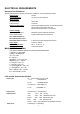
ELECTRICAL REQUIREMENTS Standard Test Conditions All tests shall be performed under the following conditions, unless otherwise specified. 225 lux Ambient light : 50 cm in front of LCD panel Viewing distance : Warrn up time All specifications : 30 minutes Fully functional : 5 seconds Chroma 2250 signal generator or equivalent, directly Measuring Equipment : Connected to the monitor under test.
Display Dot: Pixel Clock: 1280 x (RGB) × 1024 25.2 – 135.0MHz Contrast ratio: θ = 0˚ Brightness: Response time (Tr/Tf): LG: 500:1 (typical) Samsung: 700:1 (typical) AU: 550:1 (typical) LG: 250 (typical) Samsung: 300 (typical) AU: 270 (typical) LG Ta=25°C, 2/10ms (typical) Samsung AU Display color: Viewing angle(CR>10): LG Samsung AU LG Ta=25°C, 1.7/6.3ms (typical) Ta=25°C, 5.6/2.4ms (typical) 16.2M color with FRC 16.7M 16.
LCD Panel Specification LCD Panel Model • • • • • • • • • • (AU-M190EN04(V5)) Display Type active matrix color TFT LCD Resolution 1280 x 1024 pixels Display Dot 1280 x (RGB) x 1024 Display Area 376.32mm(H) x 301.06mm(V) Pixel Pitch 0.098x3mm(H) x 0.294mm(V) Display Color 16777216 Lamp Voltage 700 Vrms typ. Lamp Current 7mA rms.( typ). 4 Lamp Weight 2700g . Optical Specifications The following items are measured under stable conditions.
• • • • Lamp Voltage 650 Vrms typ. Lamp Current 7.5mA rms.( typ). 4 Lamp Weight 2250g . Optical Specifications The following items are measured under stable conditions. The optical characteristics should be measured in a dark room or equivalent state with the methods shown in Note(4). Measuring equipment : TOPCON BM-5A, BM-7, PHOTO RESEARCH PR650 (Inverter Freq.
Note 2) Definition of Contrast Ratio (CR): Ratio of gray max(Gmax),gray min(Gmin) at the center point of panel. CR= Luminance with all pixels white (Gmax) Luminance with all pixels black (Gmin) Note 3) Definition of Response time: Sum of TR , TF Note 4) After stabilizing and leaving the panel alone at a given temperature for 30 min, the measurement should be executed .Measurement should be executed n a stable, windless ,and dark room.30 min after lighting the back-light.
Optical characteristics measurement setup Notes 5) Definition of Luminance of White : measure the luminance of white at center point. Notes 6)Definition of 9 points brightness uniformity (Measuring points: Refer to the Note 5) AU BUNI= Bmin X 100% Bmax Samsumg BUNI= Bmax-Bmin X 100% Bmax Bmax: Maximum brightness Bmin: Minimum brightness Notes 7) Definition of Flicker level F Flicker Voltage pp = x 100 % LMD Voltage dc ♦ One maximum value of three estimated values.
♦ Test Point :Center point of the display area Note 8) Definition of Crosstalk (Refer to the VESA STD) The calculation for shadowing is made from the 2 luminance measurements Gbkg and Lsh, as follows: Lmax -Lmin CT = x100 % Lmin Where Lmax is the larger value of Gbkg or Lsh , and Lmin is the smaller of the two. ♦ To determine background and foreground levels (colors),first set the background to any gray scale or color level suitable for shadowing determination.
opposite boxes, A&C or B&D. Btgt will only be displayed for aligning the LMD. It will be turned off for the actual measurement. ♦ The target box point (Btgt) will be measured with the source box (Bsrc) turned on then off. (Btgt is for alignment purpose only) Display the background only at level Gbkg. Display Btgt determined in step 2 above. Using the correct distance, angle, and measurement aperture, align the LMD to the center of the Btgt. Turn off Btgt.
Interface frequency The following frequency range is generalized by supported timing. If the entered mode does not match the supported timing the display optimization will not be assured.
Supported Timing FH(KHZ) SYNC TOTAL ACTIVE SYNC FRONT FV(HZ) POLARITY (DOT/LINE) (DOT/LINE) 31.469 70.087 24.83 56.42 31.469 70.087 31.5 70.15 31.469 50.030 31.469 59.94 35.00 66.67 37.861 72.809 37.5 75 31.469 70.087 49.725 74.55 35.156 56.25 37.879 60.317 48.077 72.188 46.875 75 48.363 60.004 53.964 66.132 56.476 70.069 60.023 75.029 60.24 75.02 54.054 59.270 63.851 70.012 67.50 75.00 60.00 60.00 70.00 70.00 75.00 75.
Support Modes There will be 28 total support modes to accommodate the above mode and other video modes within the frequency range of the monitor. 85Hz refresh rate Support Monitor should display 85Hz refresh rate mode as emergency mode. Monitor should display “Out of Range” warning menu at this mode. Video input Connector Analog Video input Connector: 15pins mini D-Sub Table 2.4.5. Pin assignment for D-sub connector Separate Sync PIN NO.
Color of plastic parts: Blue (PC99) 5 1 10 6 15 11 D-sub connector Digital Video Input Connector : DVI – D (T.B.D) Table 2.4.
MONITOR BLOCK DIAGRAM The LCD monitor will contain an main board, an inverter/ power board, key board and internal adapter which house the flat panel control logic, brightness control logic and DDC. The inverter board will drive the backlight of panel and the DC-DC conversion. The Adapter will provide thr 12V DC-power to inverter/ power board.
BLOCK DIAGRAM System Block Diagram 1.
2.
3.
Monitor board layout 1. LABEL Component LABEL Component U1 24LC21A CN1 D-SVB 15 PIN U2 24LC21A CN2 DVI-D 24 PIN U3 TSU56AJ or TSU16AJ CN3 E&T 96113-0803 U4 MX10E8050IAQC CN5 P-TWO AFN300-N2G1Z 30P U5 MAX810 CN6 E&T 4500-10 U6 24LC16B CN7 E&T 4500-03 U7 APM4461 CN8 E&T 96113-1103 U8 APL1085-33CE U9 APL1117-1.
2. LABEL Component LABEL Component U3 SN74LVC14 CN1 D-SVB 15 PIN U4 NT68F633 CN3 E&T 96113-0803 U5 24LC16B CN9 E&T 4500-10 U6 NT68521 CN301 E&T 96113-1103 U10 APL1085-33CE CN302 E&T 4500-03 U13 APL1117-2.
Software flow chart - 27 -
General Instructions Press the power button to turn the monitor on or off. The other control buttons are located at front panel of the monitor. By changing these settings, the picture can be adjusted to your personal preferences. z The power cord should be connected. z Connect the video cable from the monitor to the video card. z Press the power button to turn on the monitor position. The power indicator will light up.
System Installation Connecting the Display z Power off your computer. z Connect one end of the signal cable to the LCD Monitor’s VGA port. z Connect the other end of the signal cable to the VGA port on your PC. z Make sure connections are secure. Connecting the AC Power z Connect the power cord to the LCD Monitor. z Connect the power cord to an AC power source.
Gap Spec. The step between front bezel and back cover shall be within specification. Top and Bottom Left and Right Back cover & Bezel concavity Back cover & Bezel concavity 0.8mm ≤ A ≤ 1.3 mm 0.8mm ≤ A ≤ 1.3 mm Back Cover & Hinge Cover concavity 0mm ≤ B ≤ 0.
Base & Neck concavity 0mm ≤ C ≤ 0.6mm Top and Bottom Left and Right Back cover & Bezel step Back cover & Bezel step 0mm ≤ D ≤ 0.8 mm 0mm ≤ D ≤ 0.
LCD Horizontally The angle between front bezel and LCD unit in bottom side should not large than 1.0mm. The distance of the LCD display unit from left side to right should not large than 4.0mm.
Tilt Base Rotation Tilt up 15 ± 2°/ down 5 ±2° Plastic Material For TCO99 Front Bezel Back Cover The Others For MPRII Front Bezel Back Cover The Others PC+ABS PC+ABS ABS 94HB ABS 94V-0 ABS 94V-0 ABS 94HB GAP Spec. Gap between panel with bezel is 0 mm < gap < 1.5 mm Swivel title noise spec. When adjust the monitor angle, the range should be limited -5º~ +15º and it should not have any noise.
POWER/Inverter Board Description This specification defined the performance and characteristic of power/inverter board. It supplies the following outputs : 1). 5Vdc: Logic power. 2). 5Vaudio: Audio power. 3). 15Vinv: Inverter power. Features Input Voltage: 100 ~ 240 ±10%Vac Input Frequency: 47 ~ 63Hz Input power consumption: Less than 1.2W @ minimum load Total output power: 55Wmax Inverter brightness adjustment: Burst mode Protection function: auto-recovery type Interface Signals Input 1.
2.Inverter-side connecter : SM02B-BHSS-1-TB(JST) / SM02(8.0)B-BHS-1(JST) or equivalent. PIN NO. Function Comment 1 Cth VBLH(High voltage) 2 Ctl VBLL(Low voltage) Electrical Specification: AC-DC Electrical specification 3.4.1.1 Input Specification No Item Condition Min. Typ. Max. Unit 1 Input Voltage ----- 100 --- 240 Vac 2 Input requency ----- 47 --- 63 Hz 3 Input Current ----- --- --- 1.
3.4.1.2 AC-DC Output Specification Tolerance Output Current Output oltage --- MIN MAX +5Vdc +5 /-3 % 0.05A 1.5A 4.85~5.25V dc +15Vinv +35/-5 % 0A 2A 20~14.3Vdc +5Vaudio ±5% 0A 0.6A 4.75~5.25Vdc --- 1% --- 3% --- ±5% --- --- ±5% --- Voltage Tolerance Measured at DC output terminals which are Ripple +5Vdc:50mVp-p +15Vinv:150mVp-p paralleled with a 10uf Ecap &0.1uf Ceramic cap. Noise +5Vdc:150mVp-p +15Vinv:450mVp-p 2.
Striking Time --- --- 1 --- S Lamp Current Balance --- --- ±0.35 --- mA Efficiency Vin=15V --- 80 --- % Operating Life Time --- 50000 --- --- Hr *.The open lamp voltage is testes at output connector terminal SAFETY Leakage Current: 0.
Power Consumption The monitor is equipped with a power-management according to the below. There is a delay of 5s … 7s before the transition from On-state to any power saving state to avoid unintentionally entering of a power saving stage during display resolution and timing mode changes. Transition from any power saving state to another can be instantaneous. The recovery from Off-state requires no manual power on. Mode H-Sync. V-Sync. Video Pw-cons. Indicator Rec.
Chapter 2 Operating Instructions CONTROLS Control panel (monitor front panel) 1. Power ON/OFF switch, push to ON and push to OFF. (toggle switch) 2. Power LED, will be green when monitor is on; be amber when in power saving mode. 3. Function select. 4. Adjust increase. 5. Adjust decrease. 6. Auto adjust.
Main OSD Menu: Outline: (option) The description for control function : Main Menu Sub Menu Sub Menu Icon Item Icon Contrast Description Adjustment Reset Value Range Contrast from Digital-register.
English N/A Set OSD display language to N/A be set to English. English. 繁體中文 N/A The Language will Set OSD display language to N/A Tranditional Chinese. Deutsch N/A Set OSD display language to N/A German. Français N/A Set OSD display language to N/A French. Español N/A Set OSD display language to Spain. N/A Italiano N/A Set OSD display language to Italian. N/A 简体中文 N/A Set OSD display language to N/A Simplified Chinese. 日本語 N/A Set OSD display language to N/A Japanese. H.
OSD Message: Outline: The description for OSD Message : Item Description Auto Config When User Press Hot-Key “Auto”, will show this message, and the monitor do the auto config Please Wait function. Input Not When the Hsync Frequency, Vsync Frequency or Resolution is out of the monitor support range, Supported will show this message. This message will be flying. Cable Not When the video cable is not connected, will show this message. This message will be flying.
1) Bright Adjust Brightness and Contrast value to Max. 2) Auto Balance Adjust each R, G, B contrast (gain) and offset. Method of auto adjust is depends on hardware. Adjusted value of R, G, B gain shall be used for initial value of Contrast in user menu. All value shall be adjustable manually. This function shall be located in 3. tag of Factory menu. 3) Factory color temp data edit Following data for color temp shall be editable manually. -color temp default preset No.
Plug and play Plug & play DDC2B feature This monitor is equipped with VESA DDC2B capabilities according to the VESA DDC STANDARD. It allows the monitor to inform the host system of its identity and, depending on the level of DDC used, communicate additional information about its display capabilities. The communication channel is defined in two levels, DDC2B. 2 The DDC2Bis a bidirectional data channel based on the I C protocol. The host can request EDID information over the DDC2B channel.
White Color Temperature White color temperature is 4 preset as 9300, 7500,6500 and User, Default value of user color should be user which is maximum setting for panel. Target of color setting Color Color Coordinate Tolerance Color Coordinate Tolerance Temp. x y 9300K 0.283 0.297 6500K 0.313 0.329 User - - u’ v’ +0.03 0.189 0.446 u’v’ < 0.01* +0.03 0.198 0.469 u’v’ < 0.01* - - - *) TCO’0X A.2.6.
Electrical characteristics (Tamb=25°) Audio amplifier(USE Panasonic VP-7723A Audio Analyzor. ) Item Audio Input Freq. Comment Spec. Min. Typ. Max. - 0.5Vm - Input Voltage(V) s Input Current(m A) - 500 800 - - 6dB Audio Voltage Gain 500m Vrms 1KHz Frequency Response 500m Vrms 300Hz-20KH -10dB Volume Max.,load 4 Ω - +10d B Volume Max.,load 4 Ω - -40dB Volume Max.
Chapter 3 Machine Disassembly and Replacement Disassembly Procedure Disassemble the base 1. Remove the neck cover. 2. Remove the four screws to release the hinge. 3. Remove the base Disassemble the chassis 1. Remove the four screws to release the back cover. 2. Remove the two screws to release the EMI cover from chassis. 3. Remove the two screws from VGA connector. 4. Then take the chassis. 5. Remove the two screws from bezel. 6. To separate the chassis and bezel. 7.
Disassemble the main board 1. Disassemble audio line from power board. 2. Disassemble two VL-VK lines from VL board. 3. Disassemble power line from VL board. 4. Disassemble FPC line from VL board. 5. Remove the one screw to release line from Chassis. 6. Remove the three screws from Chassis and release the main board. Disassemble the power board 1. Disassemble two voltage lines from power board. 2. Remove the one screw to release line from Chassis. 3. Remove the three screws from Chassis. 4.
Disassemble the speakers 1. Remove the two screws to release line and VK board from bezel. 2. Remove the two screws to release line and chassis from bezel. 3. Remove the four screws from bezel.
Chapter 4 Troubleshooting Main Procedure 50
Power Circuit and Backlights Troubleshooting 51
Performance Troubleshooting 52
Function Troubleshooting 53
Chapter 5 Connector Information Phonejack stereo PIN1. right PIN2. Left PIN3. Gnd : CEE22 typed connector : Line-in receptacle J1 1 2 3 PHONEJACK STEREO Video input Connector Analog Video input Connector: 15pins mini D-Sub Table 2.4.5. Pin assignment for D-sub connector Separate Sync PIN NO. 5 1 10 15 6 11 54 1 RED VIDEO 2 GREEN VIDEO 3 BLUE VIDEO 4 GROUND 5 GROUND 6 RED GROUND 7 GREEN GROUND 8 BLUE GROUND 9 PC5V (+5V DDC) 10 CABLE DETECTION 11 GROUND 12 SDA 13 H.
Chapter 6 FRU (Field Replaceable Unit) list This chapter gives you the FRU (Field Replaceable Unit) listing in global configurations of AL1916. Refer to this chapter whenever ordering for parts to repair or for RMA (Return Merchandise Authorization). NOTE : Please note WHEN ORDERING FRU PARTS, that you should check the most up-to-date information available on your regional web or channel(http://aicsl.acer.com.tw/spl/).
Part list No. Photo Part Name Part No.
7 Main Shield ECAR9914A00 8 MB AU:461ACQ30011 SAMSUNG:461ACQ30001 9 Power Board to MB cable AU: 453AC530051 Samsung: 453AC530051 10 Inverter Board AU: 453AC530051 Samsung: 453AC530051 11 Front Bezel FAAA6911000 12 Keyboard to MB Cable DCO20191700 58
13 Frame ECAR9915A00 14 LCD (R) AC6VA1901R0 AC6VT1901R5 15 Panel to MB cable 16 Function Board 59 NBX30001271 NBX30001600 454AC830001
A B C D 5 1 2 3 4 0 .
A B C 5 RED GRN BLU HS GND Shell (D VI-D) E DID - DVI 9 10 11 12 13 14 15 16 1 2 3 4 1 2 24LC02 NC VCC NC WP WP SCL GND SDA U2 2 (10K) VCC (10K) (10K) R26 2 4 R30 R28 R29 (10K) R27 L6 (JKMT_B201209J800TT) L0805D 1 R25 D D C- 5VC C -D 8 7 6 5 RXC+_I N R XC- _IN RX0- _IN R X 0+_IN 1 R24 RX1- _IN R X 1+_IN (BAT54C) CA2 CC CA1 D7 (0 .
A B C 6 RESET_MASCOT 3 3 3 3 3 3 3 3 3 R35 4.7K 5 RESET_MASCOT 1 2 4 4 4 4 4 4 4 4 0 .1uF 8 C36 6 C92 1 2 1 C38 22pF C37 22pF 2 BRI G H T IN T C34 BR IG H T 2 2 R3 6 1M 0 .1uF 2 0 .1 uF 2 390 1% R34 180 1 IN T 1 1 X1 14.318MHz C33 RX2+ RX2RX1+ RX1RX0+ RX0RXC+ RXCR32 1 R ED+ RED GREEN+ G REENP C -G REEN BLUE+ BLUE AHSYN C A V SY NC 10uF/ 16V# 3.
A B C D IO -P L E D -Y B ASE IO -PL ED -G 1 E MITTER D TA124EKA_PNP 3 C OLLECTOR L 5 B B 10K R42 VDD VDD 1 R64 2 100 R1206D D T A1 24EKA_PNP 2 100 R1206D Q2 1 R61 D T A1 24EKA_PNP 10K R43 VDD 8 7 6 5 Q1 DCABLE- DETECT ACABL E-DETECT IN T PANE L_VCTL BLKT_EN+ P ower LED Pull high design 4 DCABLE- DETECT 3 ACABL E-DETECT 5 IN T 7 PANE L_VCTL 8 BLKT_EN+ 3, 4 D DC - W P 1 2 1 2 E C E DD C - S C L-A DD C - SDA- A PLED- G H PLED - Y 3 3 RP 3 10K 1 VCC 3 Reset 2
A B 10K 2 R90 1 1 2 2SC2411K Q8 10K + 5 R89,R90,Q8, f or nest version VL -922 rev.0A 6 PANEL_VCTL 0# 2 R88 1 R88 for current PC B VL-922 rev. 0 R89 R68 1 0805 0.01uF C53 PAN5V C66 10uF 33K 2 1000uF/10V C50 2 C 8 1 4 2SC2411K Q6 10K R65 PAN5V LCD PANEL POWER CONTROL (Main) 1 2 D S1 S2 S3 G U7 D4 D3 D2 D1 8 7 6 5 L0805D 2 100uF/16V C52 L8 1 0.1uF C51 3 Vds -24V Vgs = -2.5V/-4.
A B C 8 7 6 5 4 3 2 1 8 7 6 5 4 3 2 1 E&T 4500-10 CN6 5 47uF/16V + C73 0.1uF C68 0.1uF C54 BLT_ON 220uF/10V + C64 220uF/10V + C56 R77 R71 0.01uF C65 R80 4.7K 4 NC/0 1K R74 620 B Q7 0805 0# R84 VCC R107 MMBT3904 1 Q4 R79 10K 10K R76 R87 R78 DTC124EKA_NPN 22K 22K 10K VCC L11 JKMT_B201212K800TM VCC PAN5V PAN5V JKMT_B201212K800TM For logic:+5V 0.01uF C57 L9 4 C E D 5 3 2 65 7 BRIGHT 3.3VDD 3.3VDD NC/2.2K 2.
1 2 3 4 Ven Vbri Vdd Vi nv R901 100K ZD901 RLZ13B A 2 FG N 3 2 1 Q902 RK7002 2 Q903 RK7002 R9 02 100K R903 10K C904 474 C903 104 C902 105 nc/0805 C909 104 C9 08 36K 0603 C907 103 X 7R C906 104 X7R C909A 10 9 8 7 6 5 4 3 2 1 R9 04 22 2 5 R802 510K/ 1206 R8 09 27K C804 2 22 Y1 C803 0.
A B C 5 LED1 LED E&T 4301-09 KEY-AUTO KEY -VAL-DEC KEY-VAL -INC KEY -F UN+ KEY -ONOFF GN D LED -G LED -Y A2 GND A1 8 7 6 5 4 3 2 1 K J1 S5 4 GND S4 GND TACK S1 S3 2 GND 1 A u to TACK S2 S2 M e nu 2 GND 1 4 3 TACK S3 3 2 GND 1 D 5 2 1 TACK S4 2 TACK S5 D ate: Size A 1 PCB Name-Rev : VK922-0 2 Friday, April 29, 2005 Document Nu mber 404AC8 SCHEMATIC, KEY/B VK-922, LAA698 Sheet 3 1 of Page_2 3 Rev 0A *The mark "#" to indicate that Part disuse.