V360 Smartphone Service Guide Service guide files and updates are available on the ACER/CSD web; for more information, please refer to http://gcsd.acer.com.
Revision History Please refer to the table below for the updates made on the V360 smartphone service guide.
Copyright Copyright © 2011 by Acer Incorporated. All rights reserved. No part of this publication may be reproduced, transmitted, transcribed, stored in a retrieval system, or translated into any language or computer language, in any form or by any means, electronic, mechanical, magnetic, optical, chemical, manual or otherwise, without the prior written permission of Acer Incorporated. Disclaimer The information in this guide is subject to change without notice.
Conventions The following conventions are used in this manual: SCREEN MESSAGES Denotes actual messages that appear on screen. NOTE Gives bits and pieces of additional information related to the current topic. WARNING Alerts you to any damage that might result from doing or not doing specific actions. CAUTION Gives precautionary measures to avoid possible hardware or software problems. IMPORTANT Reminds you to do specific actionsm relevant to the accomplishment of procedures.
Preface Before using this information and the product it supports, please read the following general information. 1. This Service Guide provides you with all technical information relating to the BASIC CONFIGURATION decided for Acer's "global" product offering. To better fit local market requirements and enhance product competitiveness, your regional office MAY have decided to extend the functionality of a machine. These LOCALIZED FEATURES will NOT be covered in this generic service guide.
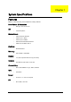
Table of Contents System Specifications 1 Features . . . . . . . . . . . . . . . . . . . . . . . . . . . . . . . . . . . . . . . . . . . . . . . . . . . . . . . . . . . .1 System Block Diagram . . . . . . . . . . . . . . . . . . . . . . . . . . . . . . . . . . . . . . . . . . . . . . . . .3 Your Acer Smartphone Tour . . . . . . . . . . . . . . . . . . . . . . . . . . . . . . . . . . . . . . . . . . . . .4 Views . . . . . . . . . . . . . . . . . . . . . . . . . . . . . . . . . . . . . . . . . . . . . . . .
Table of Contents Main Camera . . . . . . . . . . . . . . . . . . . . . . . . . . . . . . . . . . . . . . . . . . . . . . . . . . .48 Sub Camera . . . . . . . . . . . . . . . . . . . . . . . . . . . . . . . . . . . . . . . . . . . . . . . . . . . .48 Gsensor . . . . . . . . . . . . . . . . . . . . . . . . . . . . . . . . . . . . . . . . . . . . . . . . . . . . . . .49 ALS/PS . . . . . . . . . . . . . . . . . . . . . . . . . . . . . . . . . . . . . . . . . . . . . . . . . . . . . . . .49 Bluetooth . . . . .
Chapter 1 System Specifications Features Below is a brief summary of the smartphone’s many features: Form Factor & Dimension • Bar Type, 130 x 67 x 9.9 mm • Android Jelly Bean OS Modes/Bands • HSPA Dual-band 900/2100 • HSDPA up to 7.2Mbps • HSUPA up to 5.76Mbps • GSM Qual-band 850/900/1800/1900 • EDGE class 12/GPRS class 12 Platform • Mediatek MT6577 Memory • 8Gb LPDDR2 + 4GB eMMC Display • 4.
Keys/Switches • Cap Touch Key for Back/Home/Menu • Side Key: Power key, Volume up/down Battery • 1760mAh Expansion Slot • Micro SD Memory Card • DSDS, 3-color LED Indicator, SRS Others Optional • NFC Accessory • Chapter 1 Headset, Adaptor, USB Cable, Battery 2
System Block Diagram 5 4 3 2 1 D D MCU JTAG 4GB eMMC+ 8Gb DDR2 Fcore4 JTAG IQ, BSI, BPI JTAG Capacitive Touch Panel JTAG EMI,MSDC0 MT6162 I2C0, EINT GPS PCM, UART3, I2S Backlight Driver G850/G900 GSM Tx S500 MT6620 G1800/1900 AntennaAntenna WiFi/BT MSDC3 Speaker (mono diff) Band 1 PA FLASH C Band 2 PA Flash LED MT6329 I2C2 Camera IF, I2C1 Main Camera UMTS Tx Class D / Class AB (HPRP) MT6577 Camera IF, I2C1 Duplexer Band 2 C Band 8 PA BC8 share Tx path with BC5 Hea
Your Acer Smartphone Tour After examining your smartphone features, let us show you around your new smartphone. Views 1. Bezel Plastic/Painting/Soft touch Black 2. Power key Plastic/Painting/Matte Red 3. Receiver mesh Plastic mesh,d0.3/p0.45 Painting/Matte Red 9. Speaker mesh Stainless/etching 10. Circle brush/PVD Meet Black 4. TP frame Plastic/PC Glossy Black 11. Camera ring Aluminium Diamond cut/陽極髮絲紋 12. Flash lens Transparent plastic 13. Camera lens Glass/back printing transparent area 8. Vol.
No. 11 Item Camera ring Description Aluminium Diamond cut/ 陽極髮絲紋 12 Flash lens 13 Camera lens Transparent plastic Glass/back printing transparent area 14 Nameplate/metal Refer to Acer-C6 15 Battery cover Plastic/Painting/soft touch Black 16 dts logo/Painting 3D pattern/recess0.
Hardware Specifications and Configurations HW Specifications Item Specification Band Dual-Band (Band 1 & Band 8) WCDMA ; Quad-band EDGE/ GPRS/ GSM Application/ Modem Processor MT6577 Power Management MT6329A RF Transceiver MT6162 Memory 8Gb LPDDR2 + 4GB eMMC MCP memory Expansion Flash Card Slot Micro SD Connectivity Bluetooth 3.0 with EDR, WiFi b/g, FM radio, 3.5mm Audio jack, microUSB2.0 HS GPS standalone and assisted Camera 5M AF camera, with flash light; VGA camera LCM 4.
Item Specification Maximum Charging Voltage 4.35V Pack capacity 1300 mAh Talk time Talk time 3G: 4 hours dependent on usage / 2G: 5 hours dependent on usage Standby 300 hours (WDCDMA) dependent on network, 300 hours (GSM) dependent on network.
Chapter 2 Software Upgrades System Requirements • • • • Microsoft® Windows XP or above P4, 2.8G and Ram 1G DDR or above Latest version of EUU (End-user Upgrade Utility / EUU_xxx.msi) Tool: USB Cable NOTE: Please make sure mobile battery power is over 50% before execute EUU. NOTE: Please disable Anti-Virus software if EUU is blocked by it.
1. Software Upgrading Acer C10 upgrading software program applies SP_Flash_Tool. Refer to the following for its specific configurations and download steps 1.1 Hardware configurations and parts requirements Chapter 2 Item Equipment Standard configuration Qty 1 PC Win2000/WinXP/Win7/USB2.
1.2 Operation steps 1.2.1 Install the upgrading tool Step 1. Open the SP_Flash_Tool_exe__v3.1236.0.zip and decompress it to SP_Flash_Tool_exe__v3.1232.0.36 folder. Step 2. Enter the SP_Flash_Tool__v3.1232.0.sn36 folder.
Step 3. Click "Flash_tool.
1.2.2 Install the download cable driver Step 1. Connect the USB cable after removing the cell phone battery and insert it into a PC, enter the device manager, the MTK USB Port will be viewed. Step 2. Right-click to update the driver software.
Step 3. Click to browse the driver software on the PC. Step 4. Select the USB VCOM Drive folder, select SP_Drivers_V1.4 and click OK.
Step 5. The PC will enter the following interface after clicking OK, Click Next. Step 6. The PC will enter the following interface after clicking OK (Safety Tips), select keep installing this driver again to install it.
Step 7. The PC will enter the interface "Install the driver". Step 8. The installation is completed.
1.2.3 Upgrading steps Step 1. Return to SP_Flash_Tool and remove the USB cable from the PC.
Step 2. Press Scatter-loading. Step 3. The following folder will pop up, select the MT6577_emmc_AA66_XXXXX. txt in image.
Step 3. The following folder will pop up.
Step 4. Press Firmware->Upgrade and connect the cell phone (with its battery installed properly) to a PC via a USB cable for upgrading.
Step 4. The following interface will pop up to prompt that the upgrading is completed after the above two interfaces appear.
Chapter 2 21
SD Card Upload SOP 1. Copy the upgrade file into root path of SD card, and then insert into phone Note. Make sure the SD card has enough free space which should be double than upgrade package, for example, 200M upgrade file needs 400M free space. 2. Keep press Vol-UP and power button for 2 seconds and enter into Select Boot Mode UI as the illustration P1. P1 3.
4. At the status of P2, press power key, then system migrate into recovery menu as below illustration P3 P3 5. At the status of P3, press Vol-up to move the option of “apply update from external sdcard”. 6.
7. At the status of P4, press Vol-up to move the cursor on the “upgrade_Acer_AV051_V360_XXXXX_XX-XXX.zip” then press Vol_down to select, then system start to upgrade as illustration P6 P5 8. When the upgrade is done, then migrate into recovery menu and show “Install from sdcard complete” on screen as below illustration P6 P6 9. At the status of P6, “reboot system now” has been selected by default and then press Vol-down to reboot phone, then complete the upgrade work 10.
Acer 22 Code Tool SOP 1. Pre-condition A: Please make sure the USB driver has been installed into your computer.Need to execute Install.bat in the USB driver folder B: The OS of your computer should be Windows XP SP3 above or Win 7 version. C: The SN_Write_tool_exe_v2.1232.0 should be ready in your computer. User could install setup.exe in the folder of SN_Write_tool_exe_v2.1232.0 until the program setup complete. 2. Install SOP A.
C: Select the Modem database and AP database. Please make sure the Modem/AP database (Normally in the SW version img folder) you are going to select is the same as the one in your mobile phone, OR you wont write SNID successfully For example: if your mobile phone has been written SW Version Acer_AV051_V360_1.000.00_GC_Gen1 Then your selected Modem Database should be the folder of Acer_AV051_V360_1.000.
F: Keep install if popup below windows until the driver install OK G: If the driver install is OK, please launch Tool again with take the battery power off->on, and execute the above procedure to load modem database and connect mobile phone H: The tool will show COM Port searching and Preloader handshake Then insert the USB cable into your mobile phone which should be power-off and the battery should be in the phone.
Chapter 3 Machine Disassembly and Replacement This chapter contains step-by-step procedures on how to disassemble and reassemble the smartphone for maintenance and troubleshooting. IMPORTANT: The use of metal tools during disassembly may damage the casing. Use plastic tools where possible. IMPORTANT: Cover the work area with a clean, dry, lint-free cloth before placing the smartphone face down.
General Information Pre-disassembly Instructions IMPORTANT: Before proceeding with the disassembly procedure, make sure that you do the following: 1. Turn off the power to the system. 2. Unplug the USB adapter and all other cables from the system. 3. Cover the work area with a clean, dry, lint-free cloth to protect the LCD panel. 4. Place the system on a flat, stable surface.
External Module Disassembly Process External Modules Disassembly Flowchart NOTE: Items enclosed with broken lines (— - - —) are optional and may not be present.
Removing the Battery Cover IMPORTANT: Cover the work area with a clean, dry, Lint-free cloth before placing the smartphone face down. 1. Remove the Battery Cover from the side as show as picture below. Removing the Battery Cover IMPORTANT: The Battery is locked in place ; do not force the Battery out of the battery bay before open in locking mechanism. 1. Gently pull down to release the Battery.
Unscrew the 6 Screws on the Rear Cover Step Screw Quantity Upp Assy TORX MA1.6 Y L2.8 DARK AISI1018 30037 6 Screw Type Remove the Low case assemblies Remove the Main Board 1. Loosen the cable head on the main board.
2. Uncover the BTB on the Main Board. 3. Uncover the Main Board. 4. Loosen the ZIF on the main board. 5.
Remove the Antenna Sub Board 1. Loosen the ZIP on the sub board. 2. Loosen the cable head on the sub board 3. Uncover the BTB on the sub board.
Replacing the Antenna Sub Board 1. Assemble back the ZIP on the sub board. 2. Contact the cable head on the sub board. 3. Cover the BTB on the sub board. Replacing the Main Board 1. Assemble the ZIF on the main board.
2. Assemble back the Main board on the Upper cover. Replacing the USB Cable 1.
Replacing the BTB Connect 1. Assemble back the BTB Connect. Replacing the Upper Case 1. Assemble the Low case and replacing. 2. Insert the 6 screw as show.
Step Screw Quantity Upp Assy TORX MA1.6 Y L2.8 DARK AISI1018 30037 6 Screw Type Replacing the Battery 1. Insert the battery into the Battery bay and lock the Battery in the place. Replacing the Battery Cover 1. Insert the Bottom of Battery Cover into the smart phone and push the Battery cover into the place.
Chapter 4 Diagnostics and Troubleshooting Diagnostic Tools and SOP This document is intended to evaluate requirements of CCI Service Engineering (CSE), a application which facilitates repairing for after service.
Hardware Diagnostics Test items of hardware components or accessory interfaces Required (Y/N) Item Name/Description Main Display LCM- White Y LCM -Black Y LCM -Red Y LCM -Green Y LCM -Blue Y LCM Back Light-High Y LCM Back Light-Med Y LCM Back Light-Low Y HID Keypad Y Audio Test tone to speaker Y MIC test Y Test tone to earphone Y Record from earphone Y Vibrator Vibrator Y BT Turn on/off Y Indicator LED light color-Red Y LED light color-Green Y LED light color-White
User Manual of Service Tool Enter FTM On Shutdown state just press VolumeDown + Power button, we can enter into the FTM., On the right is the FTM main interface, there are four options: Item Test: the FTM test items Clear Test Report: Clear test results Version: version information ShutDown: Shutdown PS: under the FTM, mainly through the volume up and down keys to operate on key confirmation key, the next key is to select key. Enter FTM test items On the right is the main menu of FTM test item.
Touch Panel After entering this test item, use your fingers to operate the screen, draw a straight line between the two red lines, horizontal 10 lines vertical 6 lines, and then automatically end the test. Keys & Vibrate Enter the Keys & Vibrate item, in turn, press the volume key, volume down key,power button, followed by the phone vibrate, then the test ends automatically and return to the main menu.
Backlight Level After entering the test item, there will be two sub-measure items Show Test Images: enter the submeasure and continuously press the button, check the display of default 8 photos is normal. Change Contrast: This sub-test item test LCD shade. Election to the measured item, and then press 5 times on key to adjust the brightness of the screen to complete the test.
SIM Detect Insert two SIM cards, the system automatically detects these two cards, and then check the detection results, select "Test Pass" or the "Test Fail" WavePlayback In turn test the left and right channels of the Speaker, to see whether the music can output from both Speaker.
Receiver Check whether the music play normal on the receiver. HeadSet Insert the headset, select "test headset", and then the music output from the left and right channels, respectively.
Headset Button Plug in your headphones before enter the test item , click the headset hook button to complete the test PhoneMic to Headset In turn to select Mic1 Mic2, and then speak to Mic1 or Mic2, check whether the sound output from the headset.
HeadsetMic to Headset Speak to Headset Mic,then check whether the Sound output from the headset. FM Radio Plug into Headphones and test the FM can receive the 100MH and 107.1MHz broadcast.
Main Camera Put the phone on the tooling, select "Preview / Capture / Strobe" to test the Camera. Previously Move the system to test focus function. Then press the Down key to test flash (record number of flash & n) and then Up key to take picture and Down key to return. Finally, based on the number of flash, select the "Test Pass with & n" Sub Camera Select the Preview / Capture, press on Up key for self-timer, and then press Down key to return.
Gsensor Put the phone on the tooling, press the key to enter the test item, wait until the phone initialization is complete. Then turn the tooling and make six faces of the tooling parallel to the ground Respectively. ALS/PS This item need to test the ALS uncover, and PS Uncover and Cover process. Put the phone into the tooling, start the test item.
Bluetooth Into the test item, after initialization into the test instrument. Use computer software to control the instrument to test. Finally, according to the test results to select the "pass or fail" Wifi Into the test items, the system will automatically find the hotspot called "TestAP" no password, then automatically end.
GPS Put the phone on the tooling,enter the test item, and then the phone is searching for satellites. mSensor Into the test item, and then hold the phone, draw an "8" to calibrate. Put the phone on the tooling with a northsouth direction placed, and finally select "Test for North" to complete the test.
Thank you!Palette Hardware Diagnostic Tool Introduction Introduction Palette is a service tool which developed by Acer software team. This is a simple test tool to supply front end operators shop or collection points for simple diagnostic testing. Installation procedure 1. Install "Acer_Palette_2.000.00_GEN.msi" at PC/NB site. 2. Execute "Palette_Main". Select "HW Diagnostic".
3. Please fill in necessary customer's data to the columns then click "Confirm". 4. At Android device, ensure micro SD card is inserted. Please enable "USB Debugging" option (tap Menu Settings Applications Development, click "USB Debugging") then contact to PC via USB cable.
5. Now HW Diagnostic status screen pop-up. Test Item 1. Diagnostic Test Menu There are 7 test items can be used in Diagnostic test. 2. LCM Tap the screen to change difference colors to check LCD. Confirm test is passed if no errors.
3. Touch Draw 4 lines on screen. Confirm test is passed if no errors. 4. SD Test SD card read/write. Select "Close" if no errors. 5. Button Press each buttons to verify the functions. Tap "Exit" to quit the test. Confirm test is passed if no errors.
6. Vibrator Tap "Test" to verify vibration function. Confirm test is passed if no errors.
7. Camera Check the camera screen is good. Press "Back" button to quit test. Confirm test is passed if no errors. 8. Audio This test verifies sound playing/recording on Speaker, Receiver and Earphone. Press "Back" button to quit the test. Confirm test is passed if no errors. 9. Tap "Exit" to quit test program on Android device.
10. Click "Finish" to complete simple diagnostic testing. Quit Palette program Tap "Exit" to close the program.
Chapter 5 Serial Number Definition The following information describes the serial number details available on the Acer product sticker. To view the serial number, remove the Back Cover and Battery (see "Disassembly Process" on page 16) as shown below: The following describes the information on the product sticker: Acer 22 Barcode Follows Code 128 standard—refer to http://www.adams1.com/pub/russadam/128code.
Chapter 6 FRU (Field Replaceable Unit) List This chapter gives you the FRU (Field Replaceable Unit) listing in global configurations of the F900 smartphone. Refer to this chapter whenever ordering for parts to repair or for RMA (Return Merchandise Authorization). Please note that WHEN ORDERING FRU PARTS, you should check the most up-to-date information available on your regional web or channel. If for whatever reasons a part number change is made, it will not be noted on the printed Service Guide.
V360 Smartphone Exploded Diagram PART NAME FPC RF CABLE CAMERA 5M MB-ASSY DUAL WATERPROOF LABEL ANTENNA BOARD SUB BOARD LCD MODULE BLACK(LCD.TP.UPPER) LOW-ASSY DUAL BATTERY COVER BLACK DUAL BATTERY COVER BLACK SINGLE NFC MAIN ANTENNA VOLUME KEY POWER KEY BLACK Chapter 6 DESCRIPTION ACER PART NO. AA66 GF-256 REV:1.0 MB/SB FPC 50.HBPH1.001 WFL2-2HF6-04K2TV-A HRS 50.HBPH1.002 CAMERA CP56A548 ABILITY KR.05M0A.001 AA66 MB+SPONGE+GASKET (Non NFC) HB.70511.00V AV30 WATERPROOF £p5mm CROSS 47.H460W.
PART NAME RECEIVER ACER PART NO. TBD AA66 RECEIVER MESH TBD SPEAKER 1 XHS160901SW45P42-02 HAOSHENG 23.HBPH1.001 SPEAKER 2 SO181238LD01 GETTOP 23.HBPH1.002 KAPTON ZIF CONNECTOR 47.HBPH1.001 RUBBER SI VGA 47.HBPH1.002 RUBBER SI P-SENSOR 47.HBPH1.003 TORX MA1.6 Y L2.8 DARK AISI1018 30037 86.HBPH1.
V360 Smartphone Spare Parts List Spare Parts List Photo Chapter 6 DESCRIPTION ACER P/N RF CABLE 50.HBPH1.002 USB CABEL BLACK HC.70211.01F FPC 50.HBPH1.001 EARPHONE HC.00111.002 BATTERY CHINA KT.0010S.006 BATTERY MAIN KT.0010S.004 BATTERY FRENCH KT.0010S.005 ADAPTER CHINA BLACK KP.0050B.003 ADAPTER UK KP.0050P.002 ADAPTER US KP.0050P.003 ADAPTER EU KP.0050P.001 MB-ASSY DUAL HB.70511.00V MB-ASSY SINGLE NFC HB.70511.00W WATERPROOF LABEL 47.H460W.005 ANTENNA BOARD 55.HBPH1.
Photo Chapter 6 DESCRIPTION ACER P/N LOW-ASSY DUAL 60.HBPH1.001 LOW-ASSY SINGLE NFC 60.HBRH1.001 BATTERY COVER BLACK DUAL 60.HBPH1.002 BATTERY COVER WHITE SINGLE 60.HBSH1.001 BATTERY COVER WHITE DUAL 60.HBQH1.001 BATTERY COVER BLACK SINGLE 60.HBRH1.002 RECEIVER 60.HBPH1.003 MAIN ANTENNA 60.HBPH1.004 VOLUME KEY 42.HBPH1.001 POWER KEY RED 42.HBPH1.002 POWER KEY BLACK 42.HBQH1.001 SPEAKER 1 23.HBPH1.001 SPEAKER 2 23.HBPH1.002 KAPTON 47.HBPH1.001 RUBBER VGA 47.HBPH1.
Photo Chapter 6 DESCRIPTION ACER P/N RUBBER P-SENSOR 47.HBPH1.003 CAMERA 5M KR.05M0A.001 SCREW 86.HBPH1.
Appendix A Online Support Information This section describes online technical support services available to help you repair your Acer device. If you are a distributor, dealer, ASP or TPM, please refer your technical queries to your local Acer branch office. Acer Branch Offices and Regional Business Units may access our website. However some information sources will require a user i.d. and password. These can be obtained directly from Acer CSD Taiwan.
Index Numerics SIM Card Removing 6 Screws on the Rear Cover Unscrew 31 System 32 Block Diagram A 3 U Antenna Sub Board Upper Case Remove 34 Replacing 35 Replacing B Replacing 36 V Battery Replacing 37 USB Cable 38 Views Battery Cover 4 Removing 31 Replacing 38 BTB Connect Replacing 37 C Conventions IV E External Module Disassembly Flowchart 30 F FRU (Field Replaceable Unit) List 60 G Group Photo Disassembly 34 L Low case assemblies Remove 32 M Main Board Remove 32