AcerView 54e (15” monitor, 13.6” viewable image) 1. Installing the Monitor Product Package Open the shipping carton and check the contents. If any item are missing or damaged, contact your dealer immediately.
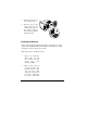
1. Turn the monitor on its side or upside-down. 2. Insert the pegs on the swivel base into the cavities at the bottom of the monitor. Push on the swivel base until the latch clicks shut. Installing the Monitor This monitor is equipped with an autosensing power supply for voltage ranges 100-120VAC/200-240VAC, 60/50 Hz. Confirm the line voltage designation on the rear panel of the monitor. Follow these steps to install the monitor: 1.
connector. 3. . Connect cable.
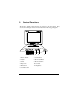
2. Control Functions The monitor digital control functions are located on the front panel. They are shown in the figure below and described in the following paragraphs. 1. Power Switch 7. Vertical Size 2. Adjust 8. Horizontal Phase 3. Select 9. Horizontal Size 4. Trapezoid 10. Contrast 5. Pincushion 11. Brightness 6.
LED indicators Each LED represents a different display adjustment. Use the Select button to choose the item to be adjusted and the Adjust button to change the setting. . Brightness: Adjusts the brightness of the display. . Contrast: Adjusts the contrast, the difference between the light and dark areas on the screen. . H-Size: Adjusts the display width (horizontal size). . H-Phase: Adjusts the horizontal position of the display (left or right). .
or bottom of the display The LED indicator goes off after 20 seconds of inactivity. If any settings have changed, the monitor automatically saves the new settings. Select button to cycle through the adjustment options to Press the or choose H-Phase, H-Size, V-Center, V-Size, Contrast, Brightness, Trapezoid, and Pincushion. The corresponding LED indicator lights up when selected. Use the Adjust buttons to change the settings.
3. How To Adjust the Monitor Press the Select key ( Press the Adjust key ( or or ) to choose the item to be adjusted. ) to change the setting. Repeat the above procedure to change other items. The monitor automatically saves the new settings after 20 seconds of inactivity. In the event that display distortion is incurred due to magnetic field interference, face the monitor to the east for the best display quality. 4.
User Setting Area The user setting area on the microcontroller maintains in its memory the last 20 display modes set by the user. You can change the settings, or add a nonstandard mode. The microcontroller always detects and displays the last mode stored in the user setting area first when the monitor is turned on. Factory Presetting Area There are 9 preferred display modes preset in the microcontroller.
5. Signal Connector Pinouts To connect VGA, 8514A or IBM-compatible graphics adapters, use a 15pin mini D-type male connector. 15-Pin Mini D-Type Male Connector User’s Guide Pin Assignment 1 2 3 4 5 6 7 8 9 10 11 12 13 14 15 Red Video Green Video Blue Video Ground Ground Red Ground Green Ground Blue Ground No Connection Sync Ground Ground Serial Data I/O H. Sync V.
6. Power Saving Feature This monitor’s power saving feature complies with these VESA power saving modes: Mode H.Sync V.Sync LED Power Consumption Normal On On Green 90 w Stand-by Off On Amber <15 w Suspend On Off Amber <15 w Off Off Off Amber Blinking <5 w The monitor uses the H.Sync and V.Sync signals to determine the operation mode to enter. The monitor power-saving feature automatically turns off H.Sync and V.
7. * Specifications Picture tube Size: Dot pitch: Surface/transmission: 15-inch (38 cm) diagonal 0.28 mm Non-glare/semi-tinted Maximum viewable size* 13.6-inch (34.
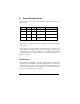
8. 12 Factory Preset Display Modes Mode Resolution V. Frequency H. Frequency VGA 640 x 400 70 Hz 31.47 KHz VGA 640 x 480 60 Hz 31.47 KHz VGA 640 x 480 72 Hz 37.86 KHz VGA 640 x 480 75 Hz 37.5 KHz SVGA 800 x 600 60 Hz 37.88 KHz SVGA 800 x 600 75 Hz 46.88 KHz SVGA 800 x 600 72 Hz 48.09 KHz Ultra VGA 1024 x 768 60 Hz 48.37 KHz SVGA 800 x 600 85 Hz 53.