Product Service Manual – X203H Service Manual for acer: X203H P/N : 9J.0VH14.T1K Applicable for All Regions Version : 001 Date : 2009/5/8 Notice: - For RO to input specific “Legal Requirement” in specific NS regarding to responsibility and liability statements. First Edition (May, 2009) © Copyright Acer Corporation 2009. All Right Reserved.
Content Index Abbreviations & Acronyms................................................................................3 1. About This Manual..........................................................................................3 1.1 Trademark ......................................................................................................... 3 2. Introduction .....................................................................................................4 2.1 RoHS (2002/95/EC) Requirements....
Abbreviations & Acronyms 1. About This Manual This manual contains information about maintenance and service of acer products. Use this manual to perform diagnostics tests, troubleshoot problems, and align the acer product. 1.1 Trademark The following terms are trademarks of Acer Inc. : Acer Importance Only trained service personnel who are familiar with this Acer Product shall perform service or maintenance to it. Before performing any maintenance or service, the engineer MUST read the “Safety Note”.
2. Introduction This section contains general service information, please read through carefully. It should be stored for easy access place for quick reference. 2.1 RoHS (2002/95/EC) Requirements – Applied to all countries require RoHS. The RoHS (Restriction of Hazardous Substance in Electrical and Electronic Equipment Directive) is a legal requirement by EU (European Union) for the global electronics industry which sold in EU and some counties also require this requirement.
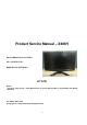
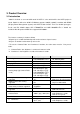
3. Product Overview 3.1 Introduction X203H is defined as our new 20’W model in ACER V series which will be the ACER project in Qisda. X203H is defined as 20’W LCD Monitor supports 1600(H) x 900(V) resolution with DPMS (Display Power Management System) and ACER eColor function. There are double input types, D-sub, and DVI. X203H adopts SEC LTM200KT03 and LGD LM200WD1-TLC1. V203H has included 1W+1W speaker.X203H also support ACM 10000:1. The features summary is shown as below, *All panel spec.
Yes Color at User preset 90-264 Volts, 47-63 Hz. No Yes <1W Yes Blue/Amber AC power input DC power input (with AC power adapter) DPMS supported LED indicator for power status showed OSD for control & information supported Yes Multi-language supported for OSD Yes Buttons control supported Yes Flywheel control supported Scaling function supported Auto adjustment function supported DDC function supported (EDID ver. 1.3) DDC-CI support version 1.
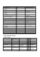
IEC1000-4-5 (Surge) CCFL operation range 90 ~ 264VAC CCFL Frequency 90 ~ 264VAC √ Common: 2KV, Differential: 1KV LGD: 2.5mA~8.0mA SEC: 3.0mA~8.5mA 40KHz ~ 70KHz Color: Black Length: 1800 +/- 50 mm Power cord √ Depends on panel source √ Depends on panel source √ 3.2.
Pin 1 2 3 4 5 6 7 8 Signal Assignment Red video Green video Blue video Ground Cable Detected Red Ground Green Ground Blue Ground Pin 9 10 11 12 13 14 15 Signal Assignment PC5V (+5 volt power) Sync Ground Ground SDA H-Sync (or H+V) V-sync SCL Note-2: The pin assignment of 24-pin DVI-D connector is as below, Pin 1 2 3 4 5 6 7 8 9 10 11 12 Signal Assignment TMDS RX2TMDS RX2+ TMDS Ground Floating Floating DDC Clock DDC Data Floating TMDS RX1TMDS RX1+ TMDS Ground Floating Pin 13 14 15 16 17 18 19 20 21 22
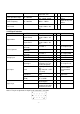
3.2.4 Scan range Item Horizontal Condition Vertical Spec 31-83 KHz 56-76 Hz OK N.A Remark √ HDMI supports √ 50Hz 3.2.5 Plug & Play DDC2B DDC-CI Support Item DDC channel type Condition Spec DDC2B EDID Version 1.3 DDC-CI Version 1.1 or Later OK N.A Remark √ Refer to S/W spec. document to see √ the detailed EDID data definition. Refer to S/W spec √ 3.2.6 Support Timings 640x480@60Hz 800 x 525 31.469 59.941 25.175 640x480@72Hz 832 x 520 37.861 72.809 31.500 640x480@75Hz 840 x 500 37.
1. Show “Input Not Supported” warning message. When Vertical Frequency is over 76Hz or under 56Hz, the display is Black and showing “Input Not Supported” warning message. (HDMI supports 50Hz for PAL video signals.) 2. If Hf /Vf is set in the range of 31KHz~83KHz and 56Hz ~76Hz, but is not the above Resolution, then it will display the nearest mode. 3.3 Operational & Functional Specification 3.3.1 Video performance *All spec. of monitor need to warm up at least 1hr.
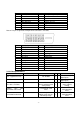
Brightness At R/G/B saturated condition 250 cd/m2 (typ.),200 cd/m2 (min) √ Response time Rising + Falling time On/off:5 ms (typ.),10ms(max) √ R/L: 85/85 degrees (typ.) 70/70 degrees (min) U/D: 75/85 degrees (typ.) 60/70 degrees(min) (0.31, 0.33) +/- (0.03, 0.03) 16.7 Millions colors √ Viewing angle At Contrast ratio = 10 At Contrast ratio = 10 CIE coordinate of White Display colors Test Condition: Set Contrast at 50, Brightness at 100, Color at User preset.
3.3.5 Transportation Item Condition Spec Test Specification: 1. Frequency Hertz 5 ~ 250 HZ , PSD Level 0.0054 (G2/Hz) (1) Vibration Package, Non-Operating 2. Grms = 1.146 3. Sweep Time : 30 minutes per Axis 4. Axes : X,Y,Z Test Spectrum: 20 Hz 0.0185(g2/Hz) 200Hz 0.0185(g2/Hz) Unpackaged, Non(2) Unpackaged Vibration Duration : 5 Minutes Operating Axis : 3 axis ( Horizontal and Vertical axis ,Z axis) 76 cm Height (MP stage) (3) Drop Package, Non-Operating (1 corner, 3 edges, 6 faces) 1.
3.3.7 EMC Item TCO03 Condition Electric Magnetic FCC part 15J class B EMI EN55022 class B Spec OK N.A Remark Band 1 < 10 V/m √ Band 2 < 1 V/m Band 1 < 200nT √ Band 2 < 25nT After Mass production under 1dBuv for constant measure. Besides DNSF √ and VCCI class-2 are optional. 3.3.8 Reliability Item Condition Spec MTBF Prediction Refer to MIL-217F > 60,000 Hours OK N.A Remark Excluding √ CCFL At 25±2 , under See Note-4 40,000 Hours (min) √ 7.
3.4 LCD Characteristics 3.4.1 The Physical definition & Technology summary of LCD panel SEC LTM200KT03 Item Condition Spec OK N.A Remark √ LCD Panel Supplier SEC Panel type of Supplier LTM200KT03 Screen Diagonal 20.0” Diagonal Display area Unit=mm 442.8(H) x 249.075(V) Physical Size Unit=mm 462.8(H) x272.0(V) x 17.5(D) Weight Unit=gram 2600 (max.) Technology Pixel pitch TN type Unit=um 276.8(H) x276.
3.4.2 Optical characteristics of LCD panel SEC LTM200KT03 Item Viewing Angle Unit [degree] [degree] [degree] [degree] Contrast ratio Response Time [msec] [msec] [msec] Color / Chromaticity Coordinates (CIE) Color Coordinates (CIE) White Luminance Uniformity [%] White Luminance @ CCFL [cd/m2] 7.0mA (center) Crosstalk (in 75Hz) [%] Conditions Min. Typ. Max.
3.5 User Controls 3.5.1 User’s hardware control definition Item Power button Auto button(Exit button) Right/Inc. button Left/Dec. button Menu button Mode button Input Select button E-Key button Mute button Condition Spec OK N.A Remark √ √ √ √ √ √ √ √ √ 3.5.
User/Text/Standard/Graphi √ c/Movie √ Acer eColor Management Exit PS: “E-key” +” Power” to enter factory mode The detailed firmware functions’ specification, please refer to C212 S/W spec. document. 3.6 Mechanical Characteristics 3.6.1 Dimension Item Bezel opening Monitor without Stand Condition Monitor with Stand W x H x D mm Carton Box (outside) L x W x H mm W x H x D mm Tilt and Swivel range Spec 444.81*251.21 mm 491.25*305.93*62.2 mm 491.25*356.53*177.
3.7 Pallet & Shipment 3.7.1 Container Specification 20' Quantity of products (sets) (Every container) 900 40' 1800 Stowing Type Container With pallet 20' Without pallet 40' Quantity of Products Quantity of pallet (sets) (sets) (Every Pallet) (Every Container) Pallet A: 90 Pallet B: Pallet A: 10 Pallet B: Pallet A: 90 Pallet B: X Pallet A: 20 Pallet B: X X X X X X X X X 3.7.2 Carton Specification 3.7.2.1 Product: Net Weight (Kg) Gross Weight (Kg) 4.1kg 5.6 kg 3.7.2.
3.8 Certification Item Environment Condition Spec OK N.A Remark Green design API Doc. 715-C49 √ Blue Angel German Standard E-2000 Switzerland EPA USA Standard TCO’99 Safety √ Microsoft Windows PC98/99 DPMS VESA DDC 2B Version 1.3 USB External CSA (Canada) √ CAN/CSA-C22.2 No.
DHHS (21 CFR) X- Ray Requirement √ DNHW PTB √ German X- Ray standard TUV / Ergo Ergonomics √ USA X- Ray Standard √ ISO 13406-2 prEN50279 3.
4. Disassembly /Assembly 4.
- 22 -
4.2 Disassembly /Assembly 4.2.1 Assembly SOP Preparation before assemble 1. Clean the room for work 2. Identify the area for material 3. Prepare the implement, equipments, materials as bellow: 1) Press-fixture 2) working table 3) Screw-driver 4) knife*1 5) glove 6) cleaning cloth 7) ESD protection item 1 2 3 picture Operation Stick the big Al tape to panel which can protect the Light-wire.
Keep the ware in. 4 Assemble the SPK to the main-SHD, the correct position reference on the picture, then the lock 4 screws to fasten it. 5 Assemble the FFC to the I/F, the correct position reference on the picture 6 Assemble the PCBA to Main-SHD 7 Lock 3 screws on the PCBA board with this order. Screw-driver Lock 2 screws on the SPS board with order.
9 Scan for fooling 10 Fasten the LVDS to panel and fix the MainBKT to CLM-F 11 Stick one Al foil on the right between pane land Main-BTK only for SEC panel 12 Stick two pieces of Al foil on the under between panel and Main-BTK only for SEC panel 13 1 2 Lock screws of side on Main-Chassis with 2/4,based on DVI. - 25 - PC Card go with panel. The position refer to the picture Screw-driver Attention the order by one to four.
14 Assemble the L-SHD the correct position reference on the picture 15 Insect the inverter wire one by one and insect the speaker wire Keep all wires in.
Not fix the panel to the edge 18 Stick an acetic tape to fix the wire one by one as the picture 19 Fix the big Al tape to panel 20 Assemble the C/B wire to the C/B connect 21 Assemble the C/B to the BZL and insert the C/B wire to the I/F BD - 27 -
22 Fix the C/B wire to the BZL 23 Check and put CLM-F on the Main-Chassis carefully. 24 Assemble the Rear Cover. 25 Check and put CLMabs on working table carefully and assemble them together - 28 - None hurt outside.
26 Assemble the Hinge to the CLM-abs 27 Lock screws*6 onto the hinge with screw-driver Screw-driver 28 Lock 4 screws to RC. (FABFDSSDA1-*** 60-80mm 2 9±1kg.
4.2.2 Disassembly SOP Preparation before disassemble 1. Clean the room for disassemble 2. Identify the area for monitor 3. Check the position that the monitors be placed and the quantity of the monitor ;prepare the area or material flow; according to the actual condition plan the disassemble layout 4.
4 Tear out the acetic tape 5 Unlock the wires.
Mylar 8 Tear down the Mylar and the tap 9 Disassembled the ACsoc shielding . 10 Unlock the LVDS wires.
13 Get off the panel from the bezel 14 Get off the big tap from the tape 15 Disassemble the control board - 33 -
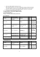
5. Level 1 Cosmetic / Appearance / Alignment Service 5.1 Alignment procedure (for function adjustment) 5.1.1 Preparation 1. Setup input timing to any preset modes or patterns. 2. Enter factory mode (press “Empowering” & “Power” buttons at the same time to turn on monitor). 3. Move cursor into “Burn-in Mode” tag and select “On” to enable burn-in mode. 4. Power off the monitor, remove the input source and then power on again. 5. Setup unit and keep it warm up for at least 30 minutes. 6.
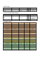
Figure-1: Preset Timing modes list 640x480@60Hz 800 x 525 31.469 59.941 25.175 640x480@72Hz 832 x 520 37.861 72.809 31.500 640x480@75Hz 840 x 500 37.500 75.000 31.500 640x480@66.66Hz 864x525 35 66.66 30.24 720x400@70Hz 900x449 31.469 70.087 28.322 800x600@56Hz 1024 x 625 35.156 56.250 36.000 800x600@60Hz 1056 x 628 37.879 60.317 40.000 800x600@72Hz 1040 x 666 48.077 72.188 50.000 800x600@75Hz 1056x625 46.875 75.000 49.500 832x624@74.55Hz 1152x667 49.722 74.
5.1.3 ADC calibration (Auto color balance adjustment) ~~Analog only, it is not required for DVI-D input source 1. Setup input timing ICL-605( 1280x1024@75Hz ), pattern 42(5-Mosaic pattern with white color block) with Analog signals from Chroma video pattern generator. (it depends on Scaler IC supplier’s recommendation) 2. Enter factory mode (press “Empowering” & “Power” buttons at the same time to turn on monitor). 3. Move cursor into “Burn-in Mode” tag and select “On” to enable burn-in mode. 4.
5. Repeat step 4 and write the digital EDID data into EEPROM for DVI-D input(ie. 24-pin DVID). 6. Read both EEPROM data and confirm it to match with the Q212 definition. (Note : The DVI-D input may not operation correctly if the digital EDID data do not exist.
5.2 Software / Firmware Upgrade Process 5.2.1 Hardware prepared: Hardware Requirement: 1. ISP board x 1 VGA signal input from 15pin Dsub cable of PC or NB. Connect to target monitor Check the Jumpers on the ISP Circuit Board (make sure J5, J6, J7, J8 are set at ping 1,2 ) Connect ISP board and PC with printer port cable 2. DSUB VGA cables x 2 3. Printer cable (with one male connector and another female connector) x 1. 4. PC or Notebook with parallel (printer) port x1.
5.2.2 Firmware Upgrade Procedure Step 1: Un-zip Port95nt and install into your computer. Step 2: Un-zip ISP application tool (RTDTool) Step 3: Press “RTD 2120 ISP” button to execute firmware program application.
Step 4: Press “64K” button to load *series*.hex file and press “64~96” button to load *extend*.hex file from your computer. Step 5: Select “Erase” option and execute lightning button first, and then select “Auto” option and execute lightning button to start upgrade firmware to the monitor.
Note: you can change program speed bar to meet your equipment speed if program firmware fail. 5.2.3 Turn Off Burn In IF the monitor without signal input has Burn In pattern. As the following figure ENTER and RIGHT to Burn In Off Press “MENU” and “>” key at the same time to exit Burn in mode(factory mode),and soft power key off/on restart the monitor.
5.3 EDID Upgrade Procedure Step 1: Run the program “Q-EDID-V012.
Note: If “VGA” choose 128bytes, and “DVI” choose 128bytes Step 2: Click “Open File” and select “VGA” or “DVI” EDID file - 43 -
Step 3: If load file is successful, it shows “Open EDID Table OK..”. And then, Click “Write EDID” button to update EDID Step 4: If write EDID is successful, it shows”Write EDID OK …” And then, Click “Read EDID” button to check if successful or not.
Step 5: If read EDID is successful, it shows”Read EDID OK …” - 45 -
5.
- 47 -
- 48 -
- 49 -
- 50 -
6. Level 2 Circuit Board and Standard Parts Replacement 6.1 Trouble Shooting Guide 6.1.1 No Display or display is unstable (Interface Board) Screen is Blank and Power LED is White. OSD shown when key pressed? Yes Follow instructions from OSD dialog No Keypad OK? No Proceed to “Check Control Board”. No Proceed to “Check Power Board”.
6.1.
6.1.
6.1.
6.1.
6.1.
6.2 Circuit Operation Theory I. Introduction The X203H is a 20” W (1600x900), LCD type is TN+Film and Normally White, 16.7M colors(R, G, B 6bit data + Hi-FRC data) TFT LCD with HDCP support monitor. It’s have dual (D-SUB and DVI) interface LCD monitor with a 15 pins D-sub signal cable and 24 pin DVI signal cable which support HDCP function. It’s compliant with VESA specification to offer a smart power management and power saving function.
III. Circuit Implementations: A.) THE MAIN BODY: A-1.) Interface board block diagram : IN T E R FA C E B O A R D 1600x900 LCM M CU RT D 21 20 L D C + 3 .3 V D C +1 .8 V S calar R T D 2545L H (Su p p ort H D C P) EEPRO M AT M E L 2 4C 16 DVI C TR L BD VG A (a) Circuit operations: A basic operation theory for this interface board is to convert analog signals of Red, Green and Blue to digital signals of Red, Green and Blue.
capable of expanding any source resolution to a highly uniform and sharp image or down scaling from 1980x1020, combined with the critically proven integrated 8 bit triple-ADC and patented Rapid-lock digital clock recovery system. It also support detect mode and DPMS control. 3.) RTD2120L: Control unit, it controls all the functions of this interface board, just like the OSD display setting, the adjustable items, adjusted data storage, the external IIC communication, support DDC2Bi. . 4.
#1 EMI Filter This circuit (Fig.2) is designed to inhibit electrical and magnetic interference for meeting FCC, VDE, VCCI standard requirements. L4 C602 0.1U 1 C604 2200PF 2 C603 2200PF L601 4 L3 3 75MH C601 0.1U Fig.
6.3 Spare Parts List Picture CATEGORY DESCRIPTION ACER PART NO. LCD CCFL LCD SAMSUNG 20"W HD+ None Glare LTM200KT03 TBD LF LK.20006.006 250nit 5ms 1000:1 2 CCFL(acer B/S) BOARD CONTROL BOARD 55.LBJ0Q.004 BOARD POWER BOARD SEC AUDIO 19.LHC0Q.001 BOARD MAIN BOARD SEC DUAL WITH SPEAKER 55.LHC0Q.
Cable CABLE POWER CORD US 27.LDW0Q.003 CABLE DVI CABLE 50.LBJ0Q.001 CABLE CABLE BETWEEN CONTROL BOARD AND M/B 50.LHC0Q.001 CABLE CABLE BETWEEN M/B AND POWER BOARD 50.LE10Q.001 CABLE CABLE BETWEEN M/B AND LCD PANEL 50.LGP0Q.001 CABLE SIGNAL CABLE 50.LBJ0Q.
CASE/COVER /BRACKET STAND NECK ASSEMBLY 60.LDX0Q.003 CASE/COVER /BRACKET STAND BASE DUAL ASSEMBLY 60.LDX0Q.010 CASE/COVER /BRACKET LCD BEZEL ASSY ASSEMBLY 60.LHC0Q.001 CASE/COVER BACK COVER SEC DUAL WITH /BRACKET AUDIO ASSEMBLY 60.LHC0Q.
Appendix 1 – Screw List / Torque (A) STANDARD SCREW TORQUE SPEC. ITEM 1 P/N DESCRIPTION 8F.205B4.019 SCRW MACH HEX #440*0.3" N Color Ni 8F.00518.100 SCRW TAP W/FL M3*10L(S3.8) ZN NI 3 8F.1A556.8R0 SCRW MACH PH M4*8L NI NYL NI 4 8F.5A356.8R0 5 8F.5A422.2R4 6 8F.00273.6R0 7 8F.VZ524.6R0 8 8F.5A356.120 9 8F.5A456.8R0 10 8F.WA314.8R0 11 8F.PA526.120 12 13 8F.XA326.100 8F.XA314.
14 15 M3*1.34P*8L B-ZN 8F.5A224.6R0 SCRW MACH FLAT M3*5L ZN 8F.00010.161 SCRW TAPTILE TRS W/EXT M4*8L ZN METAL NI METAL 5 Side M3*0.5 mount:3~4 Other: 4±0.6 10±1.0 M4*0.7 #2 #2 (B) SPECIAL SCREW TORQUE SPEC. ITEM P/N DESCRIPTION *SCREW Q’TYPE AND POSITION REFERRED TO C328. *NOTES: 1. (A)STANDARD SCREW TORQUE SPEC. 2. (B)SPECIAL SCREW TORQUE SPEC. 3. T: TAPPING SCREW. 4. M: MACHING SCREW. HOLE SIZE Screw MOUNTING TORQUE MATERIAL (KG-CM) (MM) Head DVI Connector D-SUB Connector SCREW TORQUE SPEC.
Appendix 2 – Physical Dimension Front View and Side view Fig.
Fig.
Appendix 3 – Interface Board - 68 -
- 69 -
- 70 -