Acer X213H (X223HQ) Service Guide 1
Service Guide Version and Revision Version Release Date Revision History TPV model A00 Nov.
Copyright Copyright © 2003 by Acer Incorporated. All rights reserved. No part of this publication may be reproduced, Transmitted, transcribed, stored in a retrieval system, or translated into any language or computer language, in any form or by any means, electronic, mechanical, magnetic, optical, chemical, manual or otherwise, without the prior written permission of Acer Incorporated. Disclaimer The information in this guide is subject to change without notice.
Preface Before using this information and the product it supports, please read the following general information. 1. This Service Guide provides you with all technical information relating to the BASIC CONFIGURATION decided for Acer's "global" product offering. To better fit local market requirements and enhance product competitiveness, your regional office may have decided to extend the functionality of a machine (e.g. add-on card, modem, or extra memory capability).
Precautions z Do not use the monitor near water, e.g. near a bathtub, washbowl, kitchen sink, laundry tub, swimming pool or in a wet basement. z Do not place the monitor on an unstable trolley, stand, or table. If the monitor falls, it can injure a person and cause serious damage to the appliance. Use only a trolley or stand recommended by the manufacturer or sold with the monitor. If you mount the monitor on a wall or shelf, uses a mounting kit approved by the manufacturer and follow the kit instructions.
Table Of Contents Chapter 1 Monitor Features ………………………………………… 7 Introduction ……………………………………… 7 Electrical Requirements ……………………………………… 8 LCD Monitor General Specification ……………………………………… 9 LCD Panel Specification ……………………………………… 10 Factory Preset Timing ……………………………………… 13 Monitor Block Diagram ……………………………………… 14 Main Board Diagram ……………………………………… 15 Software Flow chart ……………………………………… 16 Main Board Layout ……………………………………… 18 Installation ……………………………………… 19 Operating Instruct
Chapter 1 Monitor Features Introduction Scope This short specification describes the electrical, optical and functional performance requirements for a 54.68cm (21.5”) TFT LCD color monitor with VGA compatible interface. Description The LCD monitor is designed with the latest LCD technology to provide a performance oriented product with no radiation. This will alleviate the growing health concerns.
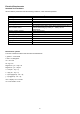
Electrical Requirements Standard Test Conditions All tests shall be performed under the following conditions, unless otherwise specified. Picture position and size Viewing angle AC Supply voltage Ambient temperature Dark room (< 1 cd/m2) 25-50 cm >30 minutes 700 mVss 6500° K Set to Factory preset value (cut off raster) Set to factory preset value, which allows that the brightest two of 32 linear distributed gray-scales (0~ 700mv) can be distinguished.
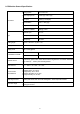
LCD Monitor General Specification Driving system TFT Color LCD Active Display Area 476.64 (H) × 268.11(V) Pixel pitch 0.282(H) x 0.282(W) Contrast Ratio 1000 : 1 Max(Typ) Response time 5ms Luminance of White 300(Typ.) cd/㎡ Separate Sync. H/V TTL H-Frequency 30kHz – 80kHz V-Frequency 55-75Hz LCD Panel Input Viewing angle ((H) 90∘+/-20∘and (V) 90∘+/-10∘ Display Colors 16.
LCD Panel Specification General Specifications Block Diagram TFT LCD Module 10
Back light Unit Electrical Characteristics 11
Optical Specifications 12
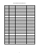
Factory Preset Timing VESA MODES Mode VGA SVGA XGA VESA SXGA WXGA WXGA+ WSXGA+ UXGA Vertical Nominal Sync Freq. Polarity +/- 1 Hz N 59.940 N Nominal Pixel Clock (MHz) 25.175 832 x 520 37.861 1024 x 625 35.156 1056 x 628 37.879 1040 x 666 48.077 1344x806 48.363 1328x806 56.476 1600 x 900 67.500 1800 x 1000 60.000 1650 x 750 44.955 1688 x 1066 63.981 1680 x 831 49.702 1792 x 795 47.712 1904 x 931 55.935 2240 x1089 65.290 2160 x 1250 75.000 2576 x 1120 67.158 2200 x 1125 67.500 2080 x 1111 66.
Monitor Block Diagram The LCD MONITOR will contain a main board, a power board and a key board which house the flat panel control logic, brightness control logic and DDC. The power board will provide AC to DC Inverter voltage to drive the backlight of panel and the main board chips each voltage. Flat Panel and CCFL backlight CCFL Drive.
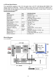
Main Board Diagram Panel Interface (CN301) Scalar IC NT68667UFG/C QFP-128L Keypad Interface (CN402) (Include MCU, ADC, OSD) (U401) D-Data D-Clock Flash Memory SST25VF010A-33-4C-SAE (U402) Crystal 12MHz (X401) DVI Connector (CN102) 15 H sync V sync RGB D-Sub Connector (CN101)
Software Flow Chart 1 Y 2 3 N N 4 N 5 Y 6 N 7 8 Y Y 9 N 10 11 Y N 12 N 13 Y Y N 14 15 Y 17 18 N 19 Y 16 16
Remark: 1) MCU initializes. 2) Is the EEPROM blank? 3) Program the EEPROM by default values. 4) Get the PWM value of brightness from EEPROM. 5) Is the power key pressed? 6) Clear all global flags. 7) Are the AUTO and SELECT keys pressed? 8) Enter factory mode. 9) Save the power key status into EEPROM. Turn on the LED and set it to green color. Scalar initializes. 10) In standby mode? 11) Update the lifetime of back light.
Main Board Layout Symbol Description Symbol Description U401 IC NT68667UFG/C QFP-128L CN402 WAFER U703 IC AP1117D33L-13 TO252-3L DIODES CN701 WAFER 9P RIGHT ANELE PITCH U103 IC AZC099-04S SOT23-6L CN301 CONNECTOR U104 IC AZC099-04S SOT23-6L X401 U402 IC SST25VF010A-33-4C-SAE CN102 DVI 24PIN CONN F CN101 U702 18 CRYSTAL 12MHz HC-49US ARG6-120 D-SUB 15PIN VERTICAL CONN WITH SCREW IC AZ1117D-1.
Installation To install the monitor on your host system, please follow the steps below: Steps 19
Chapter 2 Operating Instructions Press the power button to turn the monitor on or off. The other control buttons are located at front panel of the monitor. By changing these settings, the picture can be adjusted to your personal preferences. • The power cord should be connected. • Connect the video cable from the monitor to the video card. • Press the power button to turn on the monitor position. The power indicator will light up. External Controls Front panel controls 1.
eColor Management (OSD) Operation instructions Step 1: Press “ Key” to open the Acer e-Color Management OSD and access the scenario modes Step 2: Press “<” or “>” to select the mode Step 3: Press “Auto Key ” to confirm the mode and run Auto Adjust 22
How to Adjust a Setting 23
Adjusting the picture 24
How To Optimize The DOS-Mode Plug And Play Plug & Play DDC2B Feature This monitor is equipped with VESA DDC2B capabilities according to the VESA DDC STANDARD. It allows the monitor to inform the host system of its identity and, depending on the level of DDC used, communicate additional information about its display capabilities. The DDC2B is a bi-directional data channel based on the I²C protocol. The host can request EDID information over the DDC2B channel.
Chapter 3 Machine Disassembly This chapter contains step-by-step procedures on how to disassemble the monitor for maintenance. The tool for disassembly is as follows: Screwdriver, hexagonal screwdriver, Putty knife. Disassembly Procedure 1. Remove the hinge assembly. 2. Remove the rear cover and bezel. The arrows in blue are the hook that we should put attention to when remove the rear cover. Use plastic putty knife to release hooks, then you can easily remove the rear cover.
3. Remove the lamp connectors and remove the screws to remove the panel. Put attention to the LVDS cable.
4. Remove the screws to remove the main board and power board. 5.
Chapter 4 Troubleshooting This chapter provides troubleshooting information for the X213H: 1. No Power No power Press power key and look if the picture is normal NG Please reinsert and make sure the AC of 100-240 is normal NG OK Reinsert or check the power section Measure U703 Pin2=3.
2. No Picture (LED is orange) No picture NG The button if under control X401 oscillate waveform is normal NG Replace X401 OK OK Check reset circuit of U401 is normal NG Measure U703 Pin2=3.
3. Panel Power Circuit White screen Measure Q302 base is low level? NG OK OK Check CN301is solder and Q302,Q301 is OK? Check Correspondent component. X401 oscillate waveform is normal NG Replace X401 Check reset circuit of U401 is normal NG NG OK OK Replace U401 Replace PANEL 32 Check Correspondent component.
4.
5. Power Board 1) No power Check F801 = 14.
2.) No Backlight Check F801 = 14.5V OK NG Check adapter or MB Check ON/OFF signal OK NG Check Interface board Check U801 PIN12=14.5V OK NG Change Q802, Q804 Check U801 PIN10, 9 have the output of square wave at short time NG OK Change U801 Check Q803, Q812 PIN5, 6, 7, 8 have the output of square wave at short time.
Chapter 5 Connector Information 36
Chapter 6 FRU (Field Replaceable Unit) List This chapter gives you the FRU (Field Replaceable Unit) listing in global configurations of X213H. Refer to this chapter whenever ordering for parts to repair or for RMA (Return Merchandise Authorization). NOTE: Please note WHEN ORDERING FRU PARTS, that you should check the most up-to-date information available on your regional web or channel (http://aicsl.acer.com.tw/spl/).
ITEM PART NO.
Part List Above picture show the description of the following component. Picture Description Part No.
Main Board CBPCRNDAEQ1 Key Board KEPC7QK1 Stand Front A34G0473 RX 1B0100 Base A34G0475 RX 1B0130 Stand Rear A34G0474 RX 1B0100 Hinge A37G0050 3
Chapter 7 Schematic Diagram Main Board FB102 VGA_B+ H_Sy nc V_Sy nc R102 100R 1/10W 5% E5VCC R106 2K2 1/16W 5% R103 1K 1/16W 5% R104 1K 1/16W 5% R107 C103 C104 2K2 1/16W 5% 22pF 22pF R144 4K7 1/16W 5% 100R 1/16W 5% R101 14 13 R113 100R 1/16W 5% 11 17 DDC1_SDA DSUB_SDA 12 6 5 4 I/O4 I/O1 VDDGND I/O3 I/O2 H_Sy nc 1 2 3 FB103 V_Sy nc VGA_G+ BEAD 2 R112 DSUB_B+ R109 100R 1/16W 5% C106 0.047uF DSUB_B- R110 470R 1/16W 5% C107 1000pF DSUB_SOG R111 100R 1/16W 5% C108 0.
CN301 30 29 28 27 26 25 24 23 22 21 20 19 18 17 16 15 14 13 12 11 10 9 8 7 6 5 4 3 2 1 T0M T0P T1M T1P T2M T2P TCLK1M TCLK1P T3M T3P T4M T4P T5M T5P T6M T6P TCLK2M TCLK2P T7M T7P +5V R303 C302 10K 1/16W 5% R304 0.1uF/16V 47K 1/16W 5% C303 R307 47K 1/16W 5% R306 10K 1/16W 5% NC Q302 PPWR_ON# PANEL_VCC Q301 AO3401 C304 2N3904S-RTK/PS PANEL_VCC NC R301 C301 330 OHM 1/4W 0.1uF/16V CONN R305 C306 0.
5VCC CN701 1 2 3 4 5 6 7 8 9 SM340A D701 +5V +5V +5V 5VCC R701 NC BKLT-VBRI BKLT-EN R710 R703 R707 NC NC NC PANEL_ID# Volume# Mute CONN lock type C701 NC C703 NC C710 NC U702 NC/AIC1117A-18PE DVI_5V DSUB_5V Vin Vout 2 ADJ 2 1 3 D702 VCC1.8 E5VCC C705 + C704 NC/0.1uF/16V 1 C711 NC/100uF25V BAT54C 2 3 NC/0.1uF/16V VCC3.3 FB701 300 OHM 5VCC 1 5VCC R705 VCC3.
FB406 300OHM AVCC PVCC VCC1.8 FB403 300OHM CVDD DVDD C440 C403 C404 C448 C406 C407 C442 1uF 16V 0.1uF/16V 0.1uF/16V 0.1uF/16V 0.1uF/16V 0.1uF/16V 0.1uF/16V C401 0.22uF16V R414 10K 1/16W 5% SPI_CE SPI_SO VCC3.3 WP C447 1uF 16V 0.
Power board ! 1 R929 100 OHM 1/4W C916 0.001uF R930 100 OHM 1/4W F801 0R05 1/4W 5% +14.5V 2 + BD901 KBP208G 3 R903 100 OHM 1/4W 4 - D901 SR5150 1 2 ! C908 C912 0.1uF/25V 0.47UF C914 470pF NR901 NTCR R917 10R 1/4W 5% 1 LD7576 R934 NC 1 2 8 7 6 5 R918 10K 1/10W 1% R923 220 OHM 1/4W ! F902 + + C920 1000uF25V C925 1000uF M 16V Q901 STP9NK65ZFP FB901 BEAD U902 PC123X2Y FZOF D906 3 R919 150R 1/8W 5% R920 1K 1/10W 1% R914 43.2K OHM 1% 1/4W C924 0.
CN804 F801 1 2 +14.5V 0 OHM 1/4W R801 2.43K OHM 1% 1/10W C802 470UF/25V + Q802 PDTA144WK Q804 PDTC144WK 1 2 3 4 Q801 MMBT3904 ON/OFF S1 G1 S2 G2 D1 D1 D2 D2 OLP4 CN803 8 7 6 5 4 3 PT801 POWER X'FMR 5 1 2 +14.5V R803 10R 1/10W 5% 2 C803 D801 BAV70 6 7 MMBT2907AK Q805 C813 1N 100V NPO +/-5% 3 1 CONN R813 1K 1/10W 1% C801 NC/5pF/3KV Q803 P8008HV 1 8 CONN R808 1K 1/10W 1% 3 2 1 OLP3 2 CN801 +14.
+5V1 C609 1uF/25V 10K 1/10W 5% Lin R604 10K 1/10W 5% C606 0.47uF/16V R605 PHONEJACK 8 7 6 5 4 3 2 1 C601 0.47uF/16V Rin 10K 1/10W 5% SE/BTL LOUTP VOLUME VDD LINN LOUTN GND GND GND GND RINN ROUTN BY PASS VDD SHUTDOWN ROUTP 9 10 11 12 13 14 15 16 CN602 LOUTLOUT+ 4 3 2 1 ROUT+ ROUT- CONN C612 0.1uF/16V 100pF R608 0R05 1/8W R607 R606 15K 1/10W 5% 15K 1/10W 5% +5V1 C608 1uF/25V R601 C611 100pF U601 C610 4 5 3 2 1 C604 470UF M 16V APA2071JI-TUG 3.1W R609 CN601 0.47uF/16V R603 4.
Key board LED001 LED c GND VOL+(2K) 1.1V AUTO(1K) 0.65V ECOLOR(GND) 0 V AUTO 5 3 4 GND change Net name MENU--->AUTO AUTO----MENU GND1 GND2 GND-EMI CN001 CONNECTOR GND-EMI GND ECOLOR AUTO MENU VOL- VOL+ POWER LED OEM MODEL X173/X173W/X193W/P193W/X223W Size 絬隔瓜絪腹 T P V ( Top G2731-B-AC-X-1-070617 TPV MODEL ACER Rev Key Component 02.Key Board PCB NAME 715G2731-B-AC Date 48 Victory Electronics Sunday , June 17, 2007 Co . , Ltd.