t ne el. w.
Service Guide Version and Revision Release Date Revision History Customer model TPV model A00 Dec.-18-2008 Initial Release X233HZ&X243HQ TDRMNDD8Y1ABPN ht tp :// ww w. wj el.
Copyright Copyright © 2003 by Acer Incorporated. All rights reserved. No part of this publication may be reproduced, Transmitted, transcribed, stored in a retrieval system, or translated into any language or computer language, in any form or by any means, electronic, mechanical, magnetic, optical, chemical, manual or otherwise, without the prior written permission of Acer Incorporated. Disclaimer The information in this guide is subject to change without notice.
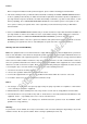
Preface Before using this information and the product it supports, please read the following general information. 1. This Service Guide provides you with all technical information relating to the BASIC CONFIGURATION decided for Acer's "global" product offering. To better fit local market requirements and enhance product competitiveness, your regional office may have decided to extend the functionality of a machine (e.g. add-on card, modem, or extra memory capability).
Precautions Do not use the monitor near water, e.g. near a bathtub, washbowl, kitchen sink, laundry tub, swimming pool or in a wet basement. Do not place the monitor on an unstable trolley, stand, or table. If the monitor falls, it can injure a person and cause serious damage to the appliance. Use only a trolley or stand recommended by the manufacturer or sold with the monitor. If you mount the monitor on a wall or shelf, uses a mounting kit approved by the manufacturer and follow the kit instructions.
7 Introduction ……………………………………… 7 Electrical Requirements ……………………………………… 8 LCD Monitor General Specification ……………………………………… 9 LCD Panel Specification ……………………………………… 10 Factory Preset Timing ……………………………………… 13 Monitor Block Diagram ……………………………………… 14 Main Board Diagram ……………………………………… 15 Software Flow chart ……………………………………… 16 Main Board Layout ……………………………………… 18 Installation ……………………………………… 19 Operating Instructions ……………………………………… 21 External Controls ……………………………………… 21
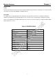
Chapter 1 Monitor Features Introduction Scope This short specification describes the electrical, optical and functional performance requirements for a 63.2cm (23.6”) TFT LCD color monitor with VGA&DVI compatible interface. Description The LCD monitor is designed with the latest LCD technology to provide a performance oriented product with no radiation. This will alleviate the growing health concerns.
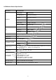
Electrical Requirements of X233HZ&X243HQ Standard Test Conditions All tests shall be performed under the following conditions, unless otherwise specified. > 30 min. AC supply voltage 230V± 5%, 50± 3 Hz Ambient temperature 20°C ± 5°C Humidity 65% ± 20% Display mode 1920 x 1080, 60 Hz, Pixel Clock:148.
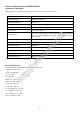
LCD Monitor General Specification Model name X233HZ&X243HQ Driving system TFT Color LCD Active Display Area 525.22 (H) x 297.22(V) Pixel pitch 0.2715(H) x 0.2715(V) Contrast Ratio 1000 : 1 (typ) Response time 5ms(Typ.). 8ms(max) Luminance of White 300 cd/m (Typ.) Separate Sync. H/V TTL H-Frequency 30kHz – 83kHz V-Frequency 56-75Hz LCD Panel (H)90 (V) 90(Type) Display Colors 16.7M Display mode 1920 x 1080 @60Hz t ne < 65W ww ON Mode w. wj Viewing angle el.
LCD Panel Specification of X233HZ&X243HQ M236H1-L01 is a 23.6” TFT Liquid Crystal Display module with 4 CCFL Backlight unit and 30 pins 2ch-LVDS interface. This module supports 1920 x 1080 Full HD mode and can display up to 16.7M colors. The inverter module for Backlight is not built in. el. ne t General Specifications Block Diagram ht tp :// ww w.
el. ne t Back light Unit ht tp :// ww w.
ht tp :// ww w. wj el.
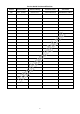
Factory Preset Timing of X233HZ&X243HQ VESA MODES Horizontal Vertical Nominal Freq. +/- 1 Hz Sync Polarity Nominal Pixel Clock (MHz) Resolution Total 640x480@60Hz 800 x 525 31.469 N 59.940 N 25.175 640x480@72Hz 832 x 520 37.861 N 72.809 N 31.500 800x600@56Hz 1024 x 625 35.156 N/P 56.250 N/P 36.000 800x600@60Hz 1056 x 628 37.879 P 60.317 P 40.000 800x600@72Hz 1040 x 666 48.077 P 72.188 P 50.000 1024x768@60Hz 1344x806 48.363 N 60.004 N 65.
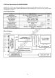
Monitor Block Diagram The LCD MONITOR will contain a main board, a power board, a usb board and a key board which house the flat panel control logic, brightness control logic and DDC. The power board will provide AC to DC Inverter voltage to drive the backlight of panel and the main board chips each voltage. Flat Panel and CCFL backlight CCFL Drive. USB board Main Board ne t Power Board el. AC-IN 100V-240V Key board ht tp :// ww w.
Main Board Diagram Panel Interface (CN301) el. ne t Crystal 12MHz (X401) Scalar IC NT68667UFG/C Flash Memory SST25VF010A (U402) .
Software Flow Chart 1 Y 2 3 N N 4 N ne t 5 Y el. 6 w.
Remark: 1) MCU initializes. 2) Is the EEPROM blank? 3) Program the EEPROM by default values. 4) Get the PWM value of brightness from EEPROM. 5) Is the power key pressed? t 6) Clear all global flags. ne 7) Are the AUTO and SELECT keys pressed? el. 8) Enter factory mode. 9) Save the power key status into EEPROM. Scalar initializes. 10) In standby mode? 11) Update the lifetime of back light. w. wj Turn on the LED and set it to green color.
Description Symbol Description U401 IC NT68667UFG/C QFP-128L CN402 WAFER U703 IC LD1117DT33TR DPAK CN701 WAFER 9P RIGHT ANELE PITCH U103 IC AZC099-04S SOT23-6L CN301 CONNECTOR U104 IC AZC099-04S SOT23-6L X401 CRYSTAL 12MHz HC-49US ARG6-120 U402 SST25VF010A-33-4C-SAE CN101 D-SUB 15PIN VERTICAL CONN WITH SCREW U702 IC AZ1117D-1.8-E1 CN102 DVI 24PIN CONN F ht Symbol tp :// ww w. wj el.
Installation To install the monitor to your host system, please follow the steps as given below: Steps 1. 1-1 Connect Video Cable a. Make sure both the monitor and computer are powered-OFF. b. Connect the VGA video cable to the computer. 1-2 Digital Cable (Only Dual-Input Model) a. Make sure both the monitor and computer are powered-OFF. b. Connect one end of the 24-pin DVI cable to the back of the monitor and connect the other end to the computer’s port. Steps 2.
Attaching / Removing the Base Install: ne t Align the release button on the bottom of the monitor with the corresponding slots on the bottom of the base. Remove: ww w. wj el. Depress the release button as indicated first before removing the base and follow the arrow direction to remove it.
Chapter 2 Operating Instructions Press the power button to turn the monitor on or off. The other control buttons are located at front panel of the monitor. By changing these settings, the picture can be adjusted to your personal preferences. • The power cord should be connected. • Connect the video cable from the monitor to the video card. • Press the power button to turn on the monitor position. The power indicator will light up. el.
ne t eColor Management (OSD) Operation instructions Key” to open the Acer e-Color Management OSD and access the scenario modes Step 2: Press “<” or “>” to select the mode Step 3: Press “Auto Key ” w. wj Step 1: Press “ el.
How to Adjust a Setting 1. Press the MENU-button to activate the OSD window. 2. Press < or > to select the desired function. 3. Press the MENU-button to select the function that you want to adjust. 4. Press < or > to change the settings of the current function. 5. To exit and save, select the exit function. If you want to adjust any other function, repeat steps 2-4. P/X Series OSD behave Acer eColor Management ww w. wj el.
Adjusting the picture ht tp :// ww The descriptions for function control LEDS w. wj el.
ww :// tp ht ne el. w.
ww :// tp ht ne el. w.
How To Optimize The DOS-Mode Plug And Play Plug & Play DDC2B Feature This monitor is equipped with VESA DDC2B capabilities according to the VESA DDC STANDARD. It allows the monitor to inform the host system of its identity and, depending on the level of DDC used, communicate additional information about its display capabilities. The DDC2B is a bi-directional data channel based on the I²C protocol. The host can request EDID information over the DDC2B channel.
Chapter 3 Machine Disassembly This chapter contains step-by-step procedures on how to disassemble the X233HZ&X243 HQ monitor for maintenance. The tool for disassembly is as follows: Screwdriver,Hexagonal screwdriver, Putty knife. Disassembly Procedure Remove the hinge assembly. :// Remove the rear cover and bezel. tp The arrows in blue are the hook that we should put attention to when remove the rear cover. Use plastic putty knife to release hooks, then you can easily remove the rear cover. ht 2.
t ne ht tp :// ww w. wj el. 3. Remove the lamp connectors and remove the screws to remove the panel. Put attention to the LVDS cable. 4. Remove the screws to remove the main board and power board.
ww :// tp ht ne el. w. wj 5.
Chapter 4 Troubleshooting This chapter provides troubleshooting information for the X233HZ&X243HQ: 1. No Power No power Press power key and look if the picture is normal NG Reinsert or check the power section w. wj OK el. Please reinsert and make sure the AC of 100-240 is normal ne t NG Measure U703 Pin2=3.
2. No Picture (LED is orange) No picture NG The button if under control X401 oscillate waveform is normal NG Replace X401 OK OK Check reset circuit of U401 is normal NG Check Correspondent component t Measure U703 Pin2=3.3V, Replace U401 el. OK NG w.
3. Panel Power Circuit White screen NG Measure Q302 base is low level? X401 oscillate waveform is normal OK NG Replace X401 ne t OK Check CN301 is solder and Q302, Q301 is OK? el. NG NG w. wj Check Correspondent component. Check reset circuit of U401 is normal OK OK ht tp :// ww Replace PANEL Replace U401 33 Check Correspondent component.
4. Key Board OSD is unstable or not working NG Connect Key Board Is Key Pad Board connecting normally? Y t NG Replace Button Switch ne Is Button Switch normally? el. Y NG Y ht tp :// ww Check Main Board Replace Key Board w.
5. Power Board 1) No power Check CN902 PIN3, 4 = 5V NG Check AC line volt 110V or 220V NG OK t Check AC input ne Check the voltage of C905 (+) NG OK w. wj Check start voltage for the pin3 of IC901 el.
2.) No Backlight Check if the input voltage of inverter part is 16V OK NG Check adapter part Check ON/OFF signal OK NG t Check Interface board OK ne Check IC801 PIN12=14.5V el. NG w.
Chapter 5 Connector Information D-sub connect and DVI connect: ww w. wj el.
Chapter 6 FRU (Field Replaceable Unit) List This chapter gives you the FRU (Field Replaceable Unit) listing in global configurations of X233HZ&X243HQ. Refer to this chapter whenever ordering for parts to repair or for RMA (Return Merchandise Authorization). NOTE: Please note WHEN ORDERING FRU PARTS, that you should check the most up-to-date information available on your regional web or channel (http://aicsl.acer.com.tw/spl/).
Item Description Part No.
Part List Above picture show the description of the following component. Description Part No. Main_frame_Sam A15G0477F01101 el. ne t Picture A34G1105 RXA1B0130 Panel 750GLM236H1112N000 Power Board PWPC8E41MQHA ht tp :// ww w.
CBPCRNDABQP Key Board KEPC7QK1 w. wj el.
Hinge A37G0110 USB7QK4 ht tp :// ww w. wj el.
Chapter 7 Schematic Diagram Main Board FB102 VGA_B+ 1 2 R105 100R 1/16W 5% C102 0.047uF DSUB_B+ R109 100R 1/16W 5% C106 0.047uF DSUB_B- R110 470R 1/16W 5% C107 1000pF DSUB_SOG R111 100R 1/16W 5% C108 0.047uF DSUB_G+ R114 100R 1/16W 5% C110 0.047uF DSUB_G- R115 100R 1/16W 5% C111 0.047uF DSUB_R+ C114 0.
CN301 30 29 28 27 26 25 24 23 22 21 20 19 18 17 16 15 14 13 12 11 10 9 8 7 6 5 4 3 2 1 T0M T0P T1M T1P T2M T2P ne t TCLK1M TCLK1P T3M T3P T4M T4P T5M T5P C302 10K 1/16W 5% R304 0.1uF/16V T6M T6P TCLK2M TCLK2P T7M T7P PANEL_VCC Q301 AO3401 47K 1/16W 5% ww C303 R307 47K 1/16W 5% NC Q302 PPWR_ON# .w j R303 el. +5V C304 2N3904S-RTK/PS NC PANEL_VCC R301 C301 CONN 330 OHM 1/4W 0.1uF/16V 0 OHM +-5% 1/8W + C305 3D tp 1 G 100uF25V 2 S AO3401L ht C306 0.
5VCC CN701 1 2 3 4 5 6 7 8 9 +5V SM340A D701 5VCC +5V +5V R701 NC BKLT-VBRI BKLT-EN R710 R703 R707 NC 4K7 1/16W 5% 4K7 1/16W 5% PANEL_ID# Volume# Mute CONN C710 NC DVI_5V DSUB_5V D702 BAT54C 3 1 3 el. 2 U702 NC/AIC1117A-18PE C711 Vout 2 C705 + C704 NC/0.1uF/16V NC/100uF25V NC/0.1uF/16V .w j 2 E5VCC Vin VCC1.
PVCC FB403 300OHM VCC1.8 CVDD DVDD C440 C403 C404 C448 C406 C407 C442 1uF 16V 0.1uF/16V 0.1uF/16V 0.1uF/16V 0.1uF/16V 0.1uF/16V 0.1uF/16V C401 0.22uF16V R414 10K 1/16W 5% SPI_CE SPI_SO VCC3.
Power board L904 100 OHM 1/4W R918 1 100 OHM 1/4W R919 +16V Coil C912 0.001uF + BD901 !GBU408 100 OHM 1/4W R920 C917 2 4 + 470UF M 35V 470UF M 35V 1 Q903 KTD1028 T901 POWER X'FMR R943 470R 1/8W 5% 4 1 D906 FMX-12SL 3 ! FB902 80OHM 2 2 ZD90 2 T ZX18B C918 + 3 R904 8.2K OHM 1/4W C905 67G315Z12115K 120uF450V ! C938 1500PF2KV R935 100 OHM 1/4W R903 NC C906 1500PF2KV 5 R946 C932 100OHM 2W R961 100 OHM 1/4W R939 1K 1/8W 5% 0.001uF L903 R905 8.
R817 +16V ZD802 RLZ5.6B ZD803 RLZ5.6B Q805 4 3 2 1 2 2 ON/OFF 4R7 1/8W 5% R816 4R7 1/8W 5% +5V R804 5K1 1/8W 5% 1 1 R803 5K1 1/8W 5% D1 D1 D2 D2 5 6 7 8 PT801 6 POWER X'FMR 7 5 AO4620 DIM C815 0.1uF R819 C802 0.047uF R802 22R 1/8W 5% Q806 4R7 1/8W 5% 4 3 2 1 R818 4R7 1/8W 5% C811 0.
+5V1 C609 1uF/25V ne t 10K 1/10W 5% R609 IC601 8 7 6 5 4 3 2 1 CN601 Lin R604 6.2KK 1/10W 5% C601 0.47uF/16V Rin C606 0.47uF/16V R605 6.2K 1/10W 5% 2 BEAD LOUT- 4 3 2 1 ROUTROUT+ CONN C608 1uF/25V R601 10K 1/10W 5% Q607 MMBT3906 :// w 1 C612 0.1uF/16V R610 10K 1/10W 5% C613 + 100uF/25V FB602 CN602 ww IN4148 2008-08-18 EE MODIFY LOUT+ R611 56K 1/10W 5% R612 10R 1/10W 5% D601 LOUTVDD LOUT+ GND GND ROUT+ VDD ROUT- 9 10 11 12 13 14 15 16 APA2069JITUL .
Key board LED001 LED 2007/5/11 c 1 3 2 A2 A1 2007/5/18 GND CN001 0 V VOL+(2K) 1.1V AUTO(1K) 0.65V ECOLOR(GND) 0 V 4 3 4 VOL+ 3 4 SW005 SW 3 2 C006 ZD002 C008 5 5 4 CN001 ECOLOR AUTO MENU VOL- GND2 GND-EMI 1 G GND-EMI 1 G GND1 GND VOL+ POWER tp CONNECTOR :// w change Net name MENU--->AUTO AUTO----MENU ww GND LED OEM MODEL X173/X173W/X193W/P193W/X223W Size 絬隔瓜絪腹 TPV G2731-B-AC-X-1-070617 TPV MODEL ACER Rev Key Component 02.
Usb board 0R05 1/10W 5% USBDN2_DP PRTPWR2 4 R737 16 120 OHM L708 NC 10K 1/10W 5% CN708 5 /OC1 R725 15K 1/10W 5% VBUS4 L706 NC LOCAL_PWR/NON_REM0/SUSP_IND VDD33 VDD33CR 35 XTAL1/CLKIN VDDA33 VDDA33 VDDA33 VDDA33/VDD33PLL 15 VCC3.3V C791 0.1uF16V 1 VDD18 14 C7102 18P 50V VSS(FLAG) VDDA18PLL 34 1 el. NC 2 .w j 0.1uF16V F704 PTCR VBUS3A1 2 FB723 120 OHM t VBUS4A 1 R723 C775 R724 0.1uF16V 10K 1/10W 5% + C774 100uF/16V /OC3 C776 C777 + 0.