TM LaneLinx User Guide UG035 (v1.0) – March 19, 2012 UG035 (v1.
Table of Contents Introduction ....................................................................................................... 3 LaneLinx Overview ............................................................................................ 3 XG_Lanelinx Details .......................................................................................... 5 LaneLinx2p5g: ....................................................................................................................... 5 Link_FSM: ...
Introduction LaneLinxTM is a lightweight, multi-gigabit per second serial protocol. It enables high bandwidth, serial connectivity with minimal programmable resource requirements, enabling lightweight, high performance data links between Speedster22i devices. This communication protocol goes through a number of steps to establish a reliable link. Once the link is established, data is transmitted and received.
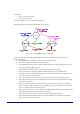
Figure 1 – LaneLinx Block diagram 4 UG035 (v1.
XG_Lanelinx Details LaneLinx2p5g: This block is the instantiation of the Hard SerDes IP contained within the Speedster22i Frame. For the included example implementation we have already created a 2.5 Gbps SerDes Macro. To change the data rate, a new SerDes Macro can be generated using the ACE IP Generator GUI. If a new macro is generated, it can simply be used as a drop in replacement for the existing one.
The signals • lane0_o_pma_txready and • lane0_o_pma_rxready are OR’ed together to create a signal called “lane_ok” The FSM diagram for Link_FSM is shown below in Figure 3. Figure 3 – Link_FSM block state diagrams In this state machine, the LINK_INITIALIZED state will ensure that both ends of the link are properly initialized. • During link training, IDLE (//I//) ordered set will be transmitted. • The receiver will constantly hunt for //I// ordered set.
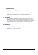
The Link_Training block This block generates the training signal for linking up the channel at the required data-rate. This block generates the transmit data and control signals, which depend on the SKIP, SYNC and SEQUENTIAL-PATTERN values. This block is also a multiplexor between the link training pattern and link initialization pattern controlled by the Link_FSM block.
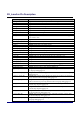
XG_Lanelinx Pin Description Signal ref_clk_p ref_clk_n resetn rx_ch0_p rx_ch0_n tx_data_valid_ch0 tx_sop_ch0 tx_eop_ch0 tx_err_ch0 tx_data_in_ch0[15:0] tx_valid_bytes_ch0 tx_ch0_p tx_ch0_n rx_data_out_ch0 [15:0] rx_valid_out_bytes_ch0 rx_data_valid_ch0 rx_sop_ch0 rx_eop_ch0 rx_err_ch0 tx_ready_ch0 serdes_tx_clk_ch0 serdes_rx_clk_ch0 MISCELLENEOUS PINS debug_bus0[4:0] debug_bus1[17:0] sig_detect_ch0 link_initialized_ch0_tx rx_data_is_good_ch0 rx_switch_data_ch0 rx_skip_ch0 rx_sync_ch0 rx_skip_sync_ch0 rx_syn
Reference Design The Reference Design consists of two blocks, TX_data_gen and RX_data_comp. 1. TX_data_gen: This block generates data which is transmitted through a parallel interface to the LaneLinx Macro. The block also generates Start-of-Packet and End-of-Packet signals depending on whether the signal “tx_ready” is asserted by XG_LaneLinx block. 2. RX_data_comp: After transmission has completed the LaneLinx protocol does the RX-data comparison to see that the RX side packet reception is OK or not.