Speedster22i Snapshot User Guide UG016 – September 22, 2014 UG016, September 22, 2014 1
Copyright Info Copyright © 2014 Achronix Semiconductor Corporation. All rights reserved. Achronix is a trademark and Speedster is a registered trademark of Achronix Semiconductor Corporation. All other trademarks are the property of their prospective owners. All specifications subject to change without notice. NOTICE of DISCLAIMER: The information given in this document is believed to be accurate and reliable.
Table of Contents Copyright Info .................................................................................................... 2 Table of Contents .............................................................................................. 3 Snapshot Overview ........................................................................................... 4 General Description and Architecture ............................................................. 5 JTAP Interface .................................
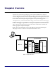
Snapshot Overview Snapshot is the real-time design debugging tool for Speedster22iHD FPGAs. Snapshot, which is embedded in the ACE Software, delivers a practical platform to evaluate the signals of a user’s design in real-time. To run the Snapshot debugger tool, the Snapshot macro needs to be instantiated inside the RTL. After instantiating the macro and programming the device, the user will be able to debug the design through the ACE Snapshot Debugger GUI.
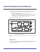
General Description and Architecture The Snapshot macro samples user-signals in real time, and sends the captured data back through the JTAG interface. The implementation supports the following features: - Capture up to 144-bit wide data. Capture always 1024 samples of data at the user clock frequency Supports up to three separate 36-bit trigger conditions, each capable of operating on any user signal.
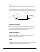
Trigger Detector As illustrated in Figure 3, the Trigger Detector receives one 36-bit each from the trigger pattern (pattern_in), don’t care sequence (mask), and input data (channel_in). For every channel_in sample, this block evaluates a corresponding match signal, called match_out. If the corresponding mask bit is set high, match_out is asserted; otherwise, match_out remains low, and is only asserted if the corresponding channel_in bit matches the pattern_in bit.
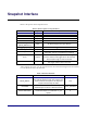
Snapshot Interface Below is the port list of the Snapshot macro: Table 1: Pin Descriptions of Snapshot Macro Pin Name tck rstn tdi tms tdo Monitor_ch [MNTR_WIDTH-1:0] trigger_ch [35:0] usr_clk Type Input Input Input Input Output Description JTAG test clock JTAG test reset (active low) JTAG test data in JTAG test mode select JTAG test data out Input 36-144 bit tapped user logic data bus Input Input Rstn_out* Output Arm* Output Stimuli* Output 36-bit trigger channel data User clock (same as user
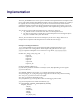
Implementation The ACX_SNAPSHOT macro is the top level module in the implementation of Snapshot. This macro exists inside the Speedster Black-Box library file (for example: speedster_bb_synplify.v for Synplify Pro users and speedster_bb_precision.v for Precision users) which must be synthesized together with the user design (instantiation example shown below). User must include the “speedster_bb*.v” file during synthesis while implementing the Snapshot macro.
.Monitor_ch(monitor_ch), .trigger_ch(trigger_ch), .rstn_out (rstn_out), .Arm (Arm), .Stimuli (Stimuli) ); /////// NOTE: Parameter value sections for Snapshot macro ////// /////// Depend on Monitor Channel width ////// /////// Below is the Table showing how the RAM size parameter //// /////// is impacted by the Monitor Channel width /////////////////////// /*************************** RAM_SIZE Monitor-Channel-Width 36 72 108 144 ***************************/ users_logic users_logic_block_instance ( .
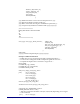
trstn : in std_logic ; tms : in std_logic ; tdi : in std_logic ; tdo : out std_logic ; usr_clk : in std_logic ; Monitor_ch : in std_logic_vector (MNTR_WIDTH-1 downto 0); trigger_ch : in std_logic_vector (35 downto 0) ; rstn_out : out std_logic ; Arm : in std_logic_vector (35 downto 0) ; Stimuli : out std_logic) ; end component ; component users_logic is port ( clk : in std_logic ; rstn : in std_logic; data_out_from_block : out std_logic_vector (MNTR_WIDTH-1 downto 0); data_for_trigger : out std_logic_vector
users_logic_block_instance: users_logic port map ( clk => usr_clk, rstn => rstn, data_out_from_block => monitor_ch_to_monitor , data_for_trigger => trigger_ch_to_trigger, snapshot_arm => arm, stimuli => stimuli); ----- END VHDL EXAMPLE --- Snapshot_top tck 36 Monitor_ch trstn 36 trigger_ch tms Arm Snap_shot_core tdi 36 tdo User Logic Stimuli rstn_out usr_clk Figure 4: Block diagram of Snapshot macro connection to user’s logic After incorporating the Snapshot macro into the design, the user
Clock constraints (SDC file): ###### CLOCK CONSTRAINTS INSIDE .SDC FILE ##### create_clock -period 10ns usr_clk create_clock –period 40ns snapshot_instance.core_y_tck ##### THIS snapshot_instance.core_y_tck IS AN INTERNAL ###### ##### TEST CLOCK GENERATED INSIDE THE SNAPSHOT-MACRO #### ##### BLOCK. IT IS MANDATORY FOR THE USER TO ####### ##### CONSTRAINT THIS CLOCK PROPERLY; OTHERWISE ####### ##### SNAPSHOT-MACRO WILL NOT WORK ON THE BOARD ######## set_false_path –from usr_clk –to snapshot_instance.
Snapshot GUI in ACE The following procedures describe how to invoke the Snapshot view in ACE. 1. Open the ACE GUI tool as shown in Figure 5. Figure 5: ACE Tool After programming the Achronix FPGA successfully, user will be ready to use the “Snapshot Debugger” tool. To go to the Snapshot Debugger tool, the user needs to click on the “Snapshot Debugger” tab from the upper left side. Then the user will see the Snapshot Debugger window as shown in Figure 6. 2.
Figure 6: Snapshot Debugger Tool view a. b. c. Select the Download tab from the GUI Specify the correct pod name in the “Specify Pod Name” box. Match the “Monitor Channel Width” size (drop-down box) to the Monitor_ch size that is connected to the snap_shot_core module inside the RTL. d. Select either “Trigger1” or “Trigger 2” or “Trigger 3”, depending on how many trigger conditions must be met before data is captured.
JTAG Scan Chain: This option has several sub-options. a. IR Bits Before Device: This option sets the number of instruction register bits before the target FPGA device. Default value is ‘0’. (e.g. There are 23 IR-Bits in Speedster/RadRunner. If the user has multiple Achronix FPGA devices being programmed on the board through the JTAG Scan Chain, the user needs to specify this bit in the box. At the end of this section this example will give an idea on how to set these values.) b.
Select Using AND: This option is used to set the trigger condition on the 72-bit bus to be captured. Select Using OR: This option is used to set the trigger condition on the particular bits of the 72-bit bus to be captured. Arm: This is to send the configuration file to the Snapshot Debugger tool, wait for the trigger condition to be met, retrieve the trace buffer contents, and output a VCD file as well as a LOG file. Cancel: This option is to direct the tool to stop the operation.
4. Save Snapshot Configuration file and Load Snapshot Configuration file: The Snapshot Debugger tool has options to save the Snapshot configuration file and to load the previously saved configuration file. Below is the table which depicts the functionality of these two options: Table 4: Snapshot view of toolbar options to save and load configuration files Icon Action Save configuration Load configuration 5.
Revision History The following table shows the revision history for this document. 18 Date Version 4/05/2013 4/17/2013 9/22/14 1.0 1.1 1.2 Revisions Initial Achronix release.