
Installation Manual
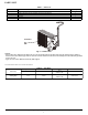


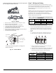
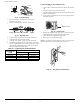
Table Of Contents
- SAFETY CONSIDERATIONS
- PARTS LIST
- WIRING
- CLEARANCES
- INSTALLATION GUIDE
- OUTDOOR UNIT INSTALLATION
- Step 1 - Select Installation Location
- Step 2 - Install the Drain Joint (Heat Pump Unit Only)
- Step 3 - Anchor the Outdoor Unit
- Step 4 - Connect the Signal and Power Cables
- Step 5 - Refrigerant Piping
- Step 6 - Evacuate Coil and Tubing System
- WIRING
- Step 7 - Electrical And Gas Leak Checks
- ELECTRICAL DATA
- CONNECTION DIAGRAMS
- SYSTEM VACUUM AND CHARGE
- START-UP
- OUTDOOR UNIT DIAGNOSTIC GUIDES
- DUCTLESS START-UP CHECKLIST - SINGLE ZONE

DLCERB: Installation Instructions
Manufacturer reserves the right to change, at any time, specifications and designs without notice and without obligations.
10
Fig. 17 — Flare Nut Spacing
f. Apply a small amount of refrigerant oil onto the flare
connection on the tubing.
g. Align the center of the pipes and/or the service valve.
Fig. 18 — Align Pipe Center
h. Connect both the liquid and gas piping to the indoor unit.
i. Tighten the flare nut with a torque wrench.
j. Using the correct wrench, grip the nut on the unit tubing.
k. While firmly gripping the nut on the unit tubing, use a torque
wrench to tighten the flare nut according to the torque values in
the Tightening Torque Requirements (Table 10). Loosen the
flaring nut slightly, then tighten again.
Table 10 — Tightening Torque Requirements
Connect Piping to the Outdoor Unit
1. Unscrew the cover from the packed valve on the side of the outdoor
unit.
2. Remove the protective caps from the valve ends.
3. Align the flared pipe end with each valve, and tighten the flare nut as
tightly as possible by hand.
4. Using a spanner, grip the body of the valve. Do not grip the nut that
seals the service valve.
Fig. 19 — Valve cover
5. While firmly gripping the body of the valve, use a torque wrench to
tighten the flare nut according to the correct torque values.
6. Loosen the flaring nut slightly, then tighten again.
7. Repeat steps 3 to 6 for the remaining pipe.
NOTE: Use a spanner to grip the main body of the valve. Torque from
tightening the flare nut can snap off other parts of the valve.
Fig. 20 — Use proper size wrenches
PIPE DIAMETER
IN.(MM)
TIGHTENING TORQUE
FT-LB N-M
Ø1/4” (6.35) 10 to 13 13.6 to 17.6
Ø3/8” (9.52) 24 to 31 32.5 to 42.0
Ø1/2” (12.7) 37 to 46 50.1 to 62.3
Ø5/8” (15.88) 50 to 60 67.7 to 81.3
Bar
Copper pipe
Clamp handle
Red arrow mark
Cone
Yoke
Handle
Bar
"A"
Indoor unit tubing Flare nut Piping
Valve cover