
Installation Manual
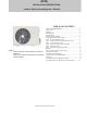
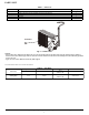
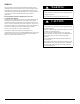
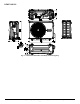

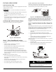

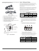
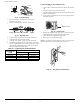
Table Of Contents
- SAFETY CONSIDERATIONS
- PARTS LIST
- WIRING
- CLEARANCES
- INSTALLATION GUIDE
- OUTDOOR UNIT INSTALLATION
- Step 1 - Select Installation Location
- Step 2 - Install the Drain Joint (Heat Pump Unit Only)
- Step 3 - Anchor the Outdoor Unit
- Step 4 - Connect the Signal and Power Cables
- Step 5 - Refrigerant Piping
- Step 6 - Evacuate Coil and Tubing System
- WIRING
- Step 7 - Electrical And Gas Leak Checks
- ELECTRICAL DATA
- CONNECTION DIAGRAMS
- SYSTEM VACUUM AND CHARGE
- START-UP
- OUTDOOR UNIT DIAGNOSTIC GUIDES
- DUCTLESS START-UP CHECKLIST - SINGLE ZONE

Manufacturer rese
rves the right to change, at any time, specifications and designs without notice and without obligations.
3
PARTS LIST
Table 1 — Parts List
Fig. 2 — Outdoor Unit
NOTES:
- If the outdoor unit is higher than the indoor unit, prevent rain from flowing into the indoor unit along the connection pipe by making a
downward arc in the connection pipe before it enters the wall to the indoor unit. This ensures that rain drips from the connection pipe before
it enters the wall.
- Figure 2 is only a sketch. Different models may differ slightly.
The units listed in Table 2 are covered in this manual.
Table 2 — Unit Sizes
Part No. Part Name Qty
1 Outdoor Unit 1
- Literature package including installation instructions and warranty 1
- Vibration pad 4
- Drain joint 1
-Drain hose 1
Ŷ2XWGRRU
Heat Pump
Sy
stem Tons BTUh V-Ph-Hz Outdoor Model
115-1
208/230-1-60
2.00
24,000
ACIQ-
24HP
Cooling Only
115-1
208/230-1-60
2.00
24,000
ACIQ-
24-HP