
Installation Manual
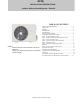
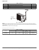
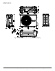

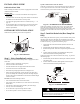

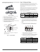
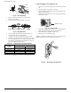
Table Of Contents
- SAFETY CONSIDERATIONS
- PARTS LIST
- WIRING
- CLEARANCES
- INSTALLATION GUIDE
- OUTDOOR UNIT INSTALLATION
- Step 1 - Select Installation Location
- Step 2 - Install the Drain Joint (Heat Pump Unit Only)
- Step 3 - Anchor the Outdoor Unit
- Step 4 - Connect the Signal and Power Cables
- Step 5 - Refrigerant Piping
- Step 6 - Evacuate Coil and Tubing System
- WIRING
- Step 7 - Electrical And Gas Leak Checks
- ELECTRICAL DATA
- CONNECTION DIAGRAMS
- SYSTEM VACUUM AND CHARGE
- START-UP
- OUTDOOR UNIT DIAGNOSTIC GUIDES
- DUCTLESS START-UP CHECKLIST - SINGLE ZONE

Manufacturer reserves the right to change, at any time, specifications and designs without notice and without obligations.
6
CLEARANCES
Fig. 7 — Clearances
Table 6 — Clearance Values
NOTE: The outdoor unit must be mounted at least 2in (50mm) above the maximum anticipated snow depth.
Fig. 8 —Clearances for multiple units
UNIT MINIMUM VALUE in. (mm)
A 24 (609)
B 24 (609)
C 24 (609)
D 4 (101)
E 4 (101)
A
D
B
Air-outlet
Air-inlet
C
E
59in (150cm)
or more when facing each other
Blowing into the air-inlet of other
condenser shall be avoided.
24in (60cm) or more
59in (150cm)
or more on a
multiple parallel unit arrangement
24in (61cm) or more on a single parallel unit arrangement
19in (48cm) or more on
a multiple parallel unit
arrangement 4in (10cm)
or more on a single
parallel unit arrangement
9.8in (25cm) or more for proper airflow
24in (61cm) or more is recommended
for service
9.8in (25cm) or more for
proper airflow 24in(61cm)
or more is
recommended
for service