
Installation Manual
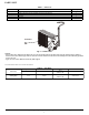
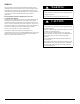
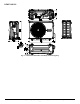

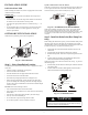

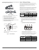
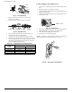
Table Of Contents
- SAFETY CONSIDERATIONS
- PARTS LIST
- WIRING
- CLEARANCES
- INSTALLATION GUIDE
- OUTDOOR UNIT INSTALLATION
- Step 1 - Select Installation Location
- Step 2 - Install the Drain Joint (Heat Pump Unit Only)
- Step 3 - Anchor the Outdoor Unit
- Step 4 - Connect the Signal and Power Cables
- Step 5 - Refrigerant Piping
- Step 6 - Evacuate Coil and Tubing System
- WIRING
- Step 7 - Electrical And Gas Leak Checks
- ELECTRICAL DATA
- CONNECTION DIAGRAMS
- SYSTEM VACUUM AND CHARGE
- START-UP
- OUTDOOR UNIT DIAGNOSTIC GUIDES
- DUCTLESS START-UP CHECKLIST - SINGLE ZONE

Manufacturer reserves the right to change, at any time, specifications and designs without notice and without obligations.
8
Step 3 - Anchor the Outdoor Unit
The outdoor unit can be anchored to the ground or to a wall-mounted
bracket with bolt (M10).
Table 7 provides a list of different outdoor unit
sizes and the distance between their mounting feet. Prepare the unit’s
installation base according to the dimensions in Table 7.
Table 7 — Unit Mounting Dimensions
Fig. 12 — Unit Air Inlet and Outlet
If you install the unit on the ground or on a concrete mounting platform,
perform the following steps:
1. Mark the positions for four expansion bolts based on the dimensions
charts.
2. Pre-drill holes for expansion bolts.
3. Place a nut on the end of the expansion bolt.
4. Hammer expansion bolts into the pre-drilled holes.
5. Remove the nuts from the expansion bolts, and place the outdoor unit
on bolts.
6. Put the washer on each expansion bolt then replace the nuts.
7. Using a wrench, tighten each nut until snug.
To install the unit on a wall-mounted bracket, perform the following
steps:
1. Mark the position of the bracket holes based on the dimensions chart.
2. Pre-drill the holes for the expansion bolts.
3. Place a washer and nut on the end of each expansion bolt.
4. Thread expansion bolts through holes in the mounting brackets.
5. Put mounting brackets in position and hammer the expansion bolts into
the wall.
6. Ensure the mounting brackets are level.
7. Carefully lift the unit and place its mounting feet on the brackets.
8. Bolt the unit firmly to the brackets.
9. If allowed, install the unit with rubber gaskets to reduce vibrations and
noise.
Step 4 - Connect the Signal and Power
Cables
The outside unit’s terminal block is protected by an electrical wiring
cover on the side of the unit. A comprehensive wiring diagram is printed
on the inside of the wiring cover.
1. Prepare the cable for connection.
Use the Right Cable
The size of the power supply cable, signal cable, fuse, and disconnect
needed is determined by the maximum current of the unit. The maximum
current is indicated on the nameplate located on the side panel of the unit.
NOTE: Select the right cable size according to the Minimum Circuit
Ampacity indicated on the nameplate of the unit.
a. Using wire strippers, strip the outer insulation from both ends
of the cable to reveal about 1.5in (40mm) of the wires inside.
b. Strip the insulation from the ends of the wires.
c. Using a wire crimper, crimp u-lugs on the ends of the wires.
2. Unscrew the electrical wiring cover and remove it.
3. Unscrew the cable clamp below the terminal block and place it to the
side.
4. Connect the wire according to the wiring diagram, and firmly screw the
u-lug of each wire to its corresponding terminal.
5. After ensuring that sure every connection is secure, loop the wires
around to prevent rain water from flowing into the terminal.
6. Using the cable clamp, fasten the cable to the unit.
7. Screw the cable clamp down tightly.
8. Insulate unused wires with PVC electrical tape. Arrange them so that
they do not touch any electrical or metal parts.
9. Replace the wire cover on the side of the unit, and screw it in place.
Fig. 13 — Cover and Screw
SYSTEM SIZE DISTANCE A IN (MM) DISTANCE B IN (MM)
24K (HP & CO) 26.1” (663) 13.9” (354)
A
B
D
Air inlet
Air outlet
Air inlet
When drilling into concrete, eye protection is recommended at
all
times.
CAUTION
Ensure the wall is made of a solid brick, concrete, or of similarity
strong material. The wall must be able to support at least four times
the weight of the unit.
CAUTION
Before performing any electrical or wiring work, turn off the main
power to the system.
WA R N I N G
All wiring work must be performed strictly in accordance with the
wiring diagram located inside the wire cover of the outdoor unit.
WA R N I N G
Cover
Screw