
Installation Manual
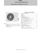
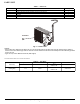
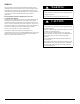
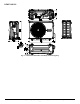

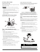

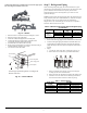
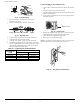
Table Of Contents
- SAFETY CONSIDERATIONS
- PARTS LIST
- WIRING
- CLEARANCES
- INSTALLATION GUIDE
- OUTDOOR UNIT INSTALLATION
- Step 1 - Select Installation Location
- Step 2 - Install the Drain Joint (Heat Pump Unit Only)
- Step 3 - Anchor the Outdoor Unit
- Step 4 - Connect the Signal and Power Cables
- Step 5 - Refrigerant Piping
- Step 6 - Evacuate Coil and Tubing System
- WIRING
- Step 7 - Electrical And Gas Leak Checks
- ELECTRICAL DATA
- CONNECTION DIAGRAMS
- SYSTEM VACUUM AND CHARGE
- START-UP
- OUTDOOR UNIT DIAGNOSTIC GUIDES
- DUCTLESS START-UP CHECKLIST - SINGLE ZONE

Manufacturer reserves the right to change, at any time, specifications and designs without notice and without obligations.
9
NOTE:
If the cable clamp resembles Figure 14, select the appropriate
hole according to the diameter of the wire.
Fig. 14 — Buckle
1. Remove the wire cover from the unit by loosening the 3 screws.
2. Remove the caps on the conduit panel.
3. Mount the conduit (field supplied) on the conduit panel.
4. Connect both the power supply and low voltage lines to the
corresponding terminals on the terminal blocks.
5. Ground the unit in accordance with local codes.
6. Be sure to leave several inches 4 to 6 inches of slack in the wiring to
facilitate installation and future service work.
7. Use lock nuts to secure the conduit.
Fig. 15 — Terminal Block
Step 5 - Refrigerant Piping
When connecting refrigerant piping, do not allow substances or gases
other than the specified refrigerant to enter the unit. The presence of other
gases or substances will lower the unit’s capacity and can cause
abnormally high pressure in the refrigeration cycle. This can cause
explosion and injury.
NOTE: The length of the refrigerant piping affects the performance and
energy efficiency of the unit. Nominal efficiency is tested on units with a
pipe length of 16.5ft (5m) (in North America, the standard pipe
length is 25ft (7.5m). A minimum pipe run of 9.8ft (3m) is required to
minimize vibration and excessive noise.
Table 8 — Maximum Length and Drop Height of Refrigerant Piping
per Unit Model
Use the following steps to connect the refrigerant piping:
1. Run the interconnecting piping from the outdoor unit to the indoor unit.
2. Connect the refrigerant piping and drain line outside the indoor unit.
Complete the pipe insulation at the flare connection then fasten the
piping and wiring to the wall as required. Completely seal the hole in
the wall.
3. Piping:
a. Cut the pipe, with a pipe cutter, at 90 degrees (see Fig. 16).
b. Remove the service connection (if provided with the unit).
Fig. 16 — Pipe Cutting
c. Remove all the burrs from the cut cross section of the pipe,
avoiding any burrs from inside the tubes.
d. Remove the flare nuts attached to the indoor and outdoor units.
e. Install the correct size flare nut onto the tubing and make the
flare connection. Refer to Table 9 for flare nut spacing.
Table 9 — Flare Nut Spacing
Three size hole: Small, Large, Medium
Buckle
G
Wire Cover
Over 1.57in.(40mm)
Terminal block
Conduit panel
Connecting cable
Power supply cord
Select the appropriate through-hole according to the
diameter of the wire.
Model Capacity
Max. Length
(ft/m)
Max. Lift (ft/m)
R410A
Fixed-speed
Split Air
Conditioner
9,000 - 12,000 82ft (25m) 33ft (10m)
18,000 98ft (30m) 66ft (20m)
24,000 164ft (50m) 82ft (25m)
OUTER DIAM.
IN (MM)
A IN (MM)
MAX. MIN.
Ø 1/4in (6.35mm) 0.05in (1.3mm) 0.03in (0.7mm)
Ø 3/8in
(9.52mm) 0.06in (1.6mm) 0.04in (1.0mm)
Ø 1/2in (12.7mm) 0.07in (1.8mm) 0.04in (1.0mm)
Ø 5/8in (15.88mm) 0.09in (2.2mm) 0.08in (2.0mm)
Oblique Rough
Warped
90°