
Installation Instructions
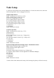

Node Setup
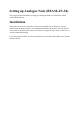
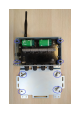
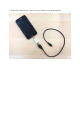
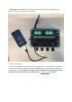
1.Connect the node antenna to the antenna bulkhead. 2. Connect the sensor wires to the node
while ensuring that the wires are plugged in correctly.
Voltage Output Sensors
PWR: +Voltage input to sensor (e.g. +12V)
GND: 0 Voltage input to sensor (e.g. 0V)
12VN: 12V Voltage input to sensor
1H: 1st channel positive output of sensor
1L: 1st channel negative output of sensor
2H: 2nd channel positive output of sensor
2L: 2nd channel negative output of sensor
+T: Thermistor
-T: Thermistor
SHLD: Shield wire of sensor
Current Loop Sensor
PWR: +Voltage inputs to sensor (e.g. +12V)
GND: Not used
12VN: Not used
1H: 1st output channel of sensor (e.g. -Voltage wire)
1L: Not used
2H: 2nd output channel of sensor (e.g. -Voltage wire)
2L: Not used
+T: Thermistor
-T: Thermistor
SHLD: Shield wire of sensor
Resistance Bridge (Wheatstone Bridge) Sensor / Potentiometer Sensor
PBRG: Positive excitation input to sensor (+5V)
GND: Ground excitation input to sensor
12VN: Not used
1H: Positive output channel of sensor (e.g. -Voltage wire)
1L: Negative output channel of sensor (applicable to Wheatstone Bridges)
2H: Not used
2L: Not used
+T: Thermistor
-T: Thermistor
SHLD: Shield wire of sensor
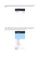
3. Switch off the Node and insert the battery while ensuring the polarity is followed correctly.