
Technical data

EDITION JUNE 2005
www.cavagnagroup.com
K
19
LPG VALVES & EQUIPMENT
DIVISION
The features described in this illustration do not bind the manufacturer.
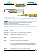
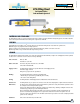
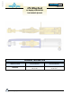
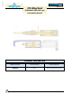
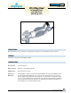
LPG Filling Head
for Bayonet Valves
Semi-automatic Operated
MATERIALS AND STANDARDS
The Filling Head is made of corrosion-resistant materials such as stainless steel,brass,aluminium and special polymers. The rubber materials
used are developed and manufactured according to the requirements of EN 549.
FEATURES
1.Insignificantlossofproduct(1cm
3
)whenthegasflowiscutoffandthefillingheadisreleasedfromthecylindervalve.
2. Balanced jig for easy suspension between filling operations.
3. Easy to manualy connect and disconnect. Filling is initiated simultaneously with the connection to the valve.
4. Slim design makes it easy to handle and it fits easily inside any shroud.
COLOUR
TheFillingHeadissuppliedinthenaturalcolorsoftherawmaterial(brassandaluminium)exceptfortheclampingbracewhichispainted
in a blue color to ensure full corrosion-resistance and longer durability.
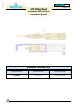
Inlet connection: LPG: 1/4” NPT.
Pneumatic air :3/8” NPT.
Outlet connection: Connects to bayonett valves G61 acc. to EN 12864
Valves with and without PRV.
Supply pressures: The Filling Head is designed to operate within the normal supply pressures.
Pneumatic supply: 6-10 bar.
Filling time as per present valve specification.
Marking: The following information is marked on the Filling Head:
•Monthandyearofproduction(postdatedbythreemonths).
•ThecodenooftheFillingHead.
Packing: The Filling Heads are individually packed in cardboard boxes without instructions.
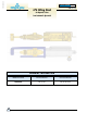
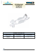
Function and The Filling Head is easy to operate. The connector at the end of the clamping brace is pushed into the undercut of
Maintenance: the bayonet. Once the Filing Head outlet is aligned with the cylinder valve outlet, the ball knob is pusched to allow
the compressed air to fill the pneumatic cylinder.
This forces the Filling head outlet to attach the cylinder valve outlet thereby obtaining a leaktight connection and
simultaneously opening the gas seals initiating the LPG flow.
After completing the filling operation the handle on the side of the pneumatic cylinder is pushed and the air
pressure isreleased thereby stopping the flow of gas and the outlet disconnects from the cylinder valve. The
connector is then removed from the valve. All rubber seals inside the gas section as well as the complete pneumatic
cylinder can be exchanged.
Suitable for: Omeca valves 66-0-290-0136, 66-0-290-0145