RALOY RACKMOUNTCONSOLES Slim 1U Rackmount LCD Monitor Optional KVM Switch USER MANUAL www.RALOY.com Copyright ® 2004 Raloy, Inc.
Content Specification……………….……………………………………………....3 Rackmount Installation…………….……….…………………..………..4 Product Detail………………………………………………………………5 On Screen Display…………………………………………...………..6 On Screen Display for KVM Operation…………………………...….13 RA15/17KVM8 Illustration……………………………………………….16 INTRODUCTION……………….……………………………….………….......16 FEATURES…………...…………………………………………………..…….16 PACKAGE CONTENTS……………...…………..………………………………17 TECHNICAL SPECIFICATIONS………..…………………………………….…….17 CONNECTOR DIAGRAMS……………………………………………...……….
Specification: Model RA15/17 RA15/17KVM8 RA15/17KVM16 Size: 1U 19” Rackmount type Keyboard: Notebook type, 105 Keys Touchpad Mouse: Dimension: 444.5 * 44.5 * 550 mm 444.5 * 44.5 * 580 mm 444.5 * 44.5 * 590 mm (17.5”*1.75”*21.6”) (17.5”*1.75”*22.8”) (17.5”*1.75”*23.2”) Weight: 15 kg(33 lb) 15 kg(33 lb) 17.
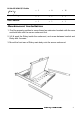
D-Sub 15 VGA-PS/2 Cable (3 in 1): Screw Package: User’s Manual: × 1 × 8 × 16 × 1 × 1 × 1 × 1 × 1 × 1 Rackmount Installation 1. Find the property position to screw these two extension brackets with the ears and both side onto the server rackmount first. 2. Lift & push the Raloy inside the rackmount, and screw between bracket and Raloy with 4 screws. 3. Mount the front ears of Raloy main body onto the server rackmount.
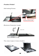
Product Detail Self-locking Device Press the button to unlock Maximum Extension Length Up To 110∘ 431.
On Screen Display Raloy Manual 6
Auto Adjustment Bright & Contrast Raloy Manual 7
Image Adjustment Raloy Manual 8
Color Adjustment Raloy Manual 9
Raloy Manual 10
Language Selection Reset Raloy Manual 11
OSD Adjustment Exit Raloy Manual 12
On Screen Display for KVM Operation When you pop up the OSD menu window go through the hot key, you will see the following small window on your monitor. a. The 1ST line bar is Bank no. BANK : 1 01 SYSTEM 01 02 ☼SYSTEM 02 ( 03 ☼SYSTEM 03 04 ☼SYSTEM 04 05 ☼SYSTEM 05 06 SYSTEM 06 07 07 08 ☼SYSTEM 08 SYSTEM b. The 2nd block is your PC system name list. You will find the system number list from 01 to 8. You can define your PC name in maximum 8 characters.
To use “ Tab “ key to select items like Bank, OSD, SCAN, CHANGE PASSWORD, CONSOLE ON/OFF, etc… OSD : 1 0 SEC. CHANGE PASSWORD SCAN: 1 0 SEC. 15 ☼SYSTEM 15 16 CONSOLE SYSTEM ON/OFF 16 OSD : 1 0 SEC. ( CHANGE PASSWORD SCAN: 1 0 SEC. CONSOLE ON/OFF ESC : QUIT ENTER :COMPLETE TAB : NEXT INSERT :EDIT a. The “ OSD: 10 SEC” means that the OSD windows display or PC system name exists 10 sec. on your monitor. You can modify it from 05 sec to 99 sec. The factory default value is 10 sec.. b.
matched or not. NEW PASSWORD ESC : QUIT COMPLETE ENTER : COMPLETE d. The “ CONSOLE ON/OFF “ means to manage the RA15/17KVM8. If you select “ CONSOLE ON “, it means that any user can use the console. If you select “ CONSOLE OFF “(factory default OFF state), it means that any user will not be allowed to use the console unless you enter the password. When you enter the password already and pass the RA15/17KVM8 authentication, the CONSOLE will be set to ON.
RA15/17KVM8 Illustration Introduction Thank you for choosing RA15/17KVM8. RA15/17KVM8 can save your MONEY, TIME, SPACE, EQUIPMENT and POWER. Controlling multiple PCs from One Keyboard, Mouse and VGA Monitor. RA15/17KVM8 is loaded with features such as 19” Rack Mount Size, Daisy Chain up to eight units, On Screen Display Menu, Password security, Searching PC server name, Hot key Control, Front Panel Push Button and Auto Scan Control.
Technical Specifications Model No. RA15/17KVM8 PC Port 8 Console Port 1 PC Port Connector (All Female Type) PS/2 Keyboard mini Din 6 pin PS/2 Mouse Mini Din 6 pin VGA HDDB 15pin Daisy Chain Port Connector (All Female Type) PS/2 Keyboard mini Din 6 pin PS/2 Mouse Mini Din 6 pin VGA HDDB 15pin PC selection On Screen Display Menu, Hot Key, Push Button 7 segment LED One Bank LED, Two PC Port LEDs On Screen Display Control Yes Scan Intervals 5~99 Sec.
Connector Diagrams PS/2 Cable: Mini Din 6 pin Male to Male VGA Cable: HDB15 pin Male to Male AT to PS/2 keyboard adapter: (Optional) Din 5 pin Male to Mini Din 6 pin Female PS2 to DB9 adapter (Optional) Mini Din 6 pin Female to DB 9 pin Female Raloy Manual 18
Hardware Installation Before installation, please make sure all of peripherals and computers have been turned off. Step 1 Now the PC connections can be made with the monitor (VGA) connections first. Connect a VGA cable (15-pin HDDB Male / Male) with the Male side to both of the PC and the rear panel of the KVM switch to the connector labeled VGA. Repeat this for all PCs. Step 2 Connect the first computer’s mouse cable to the RA15/17KVM8.
Step 6 Attach the power supply to the RA15/17KVM8 unit and plug the other end into an electrical receptacle. Now you will see the LED for Port 1 light up, and you will hear a beep. Usage The power on state of 8-port RA15/17KVM8: When you power on the RA15/17KVM8, it will ask you for the password, the default password value is eight zero –“ 00000000 “. Please key in eight zero and enter the same value at retype field.
+ Scroll Lock + + Scroll Lock + Page Down = Previous Bank = Next Bank To select Scroll Lock Scroll Lock + + Scroll Lock Scroll Lock + Bank No + B Port No = Beeper (Note: The default Beeper function is ON and beeper control is only for available for Scan Mode ) Scroll Lock + Scroll Lock + S = Auto Scan To get out of Auto Scan Mode, Press any key or SPACE bar.
Example: A. To access a computer attached to Port 6 of the fifth Bank. You can press through hot key as below: Scroll lock + Scroll lock + “5” + “0” “ 6” B. To access a computer attached from Bank 3 to Bank 4, You can press through hot key as below: Scroll lock + Scroll lock + Page Down Notice: Bank no. and Port no. Selection must be made using the numeric keys on the keyboard. Numeric keys on the keypad are not available as a hot key command.
Daisy Chain Connection Diagram Please use the attached 3 feet 3-in-one daisy chain Cable Kit to daisy chain the RA15/17KVM8. A. Connect Keyboard, Mouse and Monitor to the console port (white color block) of bank 1 RA15/17KVM8. B. Use one end of 3-in-one Cable Kit to connect the daisy chain port of bank 1 and the other end for the console port (white color block) of bank 2 RA15/17KVM8. C. Please repeat item B to daisy chain more bank as you want. But, the maximum daisy chain bank is eight. D.
Hot Plug The RA15/17KVM8 supports “Hot Plug“ function for easy addition or removal of PCs. The user can arrange or maintain PCs as follows: a. A PC can be disconnected and reconnected to the same or different port of the RA15/17KVM8 unit without having to power it off as long as it is not the Daisy-chain port or pass through port. b. You may unplug the mouse or the keyboard from the console port and plug it back in at any time. NOTICE: Some O.S.
7. If forgetting the “ password ” you typed, please contact your supplier. Accessories Ordering information: 1. VGA-100 100 feet • • • VGA Extender (DB15 Female to DB15 Female) Max distance: VGA-100 - HDDB 15 pin to HDDB 15 pin, All female, Max 100 feet. PS2-100 - Two PS/2 Mini Din 6 pin to two PS/2 Mini Din 6 pin, all female, Max 100 feet. 2. PS2-100 PC port PS2 Extender (Mini Din 6 Female to Mini Din 6 Female), MAX distance: 100 feet 3.
RA15/17KVM16 Illustration Introduction Congratulations, you have chosen the efficient RA15/17KVM16 switch can save your MONEY, TIME, SPACE, EQUIPMENT and POWER. Controlling multiple PCs from One Keyboard, Mouse and VGA Monitor. RA15/17KVM16 is loaded with features such as 19” Rack Mount Size, Daisy Chain up to 16 units, On Screen Display Menu, Password security, Searching PC server name, Hot key Control, Front Panel Push Button and Auto Scan Control.
Technical Specifications Model No.
Computer side 16 HDB 15 pin male to male VGA cables 16 PS/2 cables male to male for Keyboard 16 PS/2 cables male to male for Mouse Cable Diagrams PS/2 Cable: Mini Din 6 pin Male to Male VGA Cable: HDB15 pin Male to Male AT to PS/2 keyboard adapter: (Optional) Din 5 pin Male to Mini Din 6 pin Female PS2 to DB9 adapter (Optional) Mini Din 6 pin Female to DB 9 pin Female Raloy Manual 28
Switching Indication Hardware Installation Step 1 Connect the monitor to the RA15/17KVM16. Using the attached cable, or the one included with your monitor, connect it to the HD DB-15 female port on the back of the KVM unit labeled with the monitor symbol at the CONSOLE port connector. Step 2 Connect the keyboard to the RA15/17KVM16. If you have an AT type keyboard, you will need an AT to PS/2 adapter. Step 3 Connect the mouse to the RA15/17KVM16.
Step 5 Connect the first computer’s mouse cable to the RA15/17KVM16. If using a PS/2 cable, connect one end to the PS/2 mouse port on the computer, and the other end to the PC1 PS/2 mouse port on the back of RA15/17KVM16. If using a serial mouse cable (optional), connect one end to a DB-9 serial port on the computer, and the other end to the PC1 DB-9 serial mouse port on the back of the RA15/17KVM16. If you need Serial DB-9 to PS2 Mini Din 6 pin adapter, please contact your supplier.
NOTICE: Please be remind to plug in power adapter. Although the PCs connected to RA15/17KVM16 are able to support enough power to the stand alone switch, RA15/17KVM16 still needs a power adapter for daisy chain more banks. If you forget to plug in power adapter on the status of daisy chain, it may cause the unexpected status occurred. Usage The power on state of RA15/17KVM16 : When you power on RA15/17KVM16, it will ask you the password, the default password value is eight zero –“ 00000000 “.
Below are the different hot key commands: within 2 seconds Scroll Lock Scroll Lock + Scroll Lock Scroll Lock + ↑ + = = ↓ + Previous Channel Next Channel (Note: You also could press “up arrow key” or “down arrow key” longer time to speed up selecting the destination port) Scroll Lock Scroll Lock + Scroll Lock Scroll Lock + + Page Up + Page Down = Previous Bank = Next Bank To select PC port: Scroll Lock Scroll Lock Scroll Lock + Scroll Lock + + Bank No + B Port No.
+ = + Search the same PC name (Note: Search PC name starting from 1st PC port) FIND:█ Scroll Lock + Scroll Lock + Space bar = On Screen Display Menu Example: a. To access a computer attached to Port 6 of the fifth Bank. You can press through hot key as below: Scroll lock + Scroll lock + “5” + “0” “ 6” b. To access a computer attached from Bank 3 to Bank 4, You can press through hot key as below: Scroll lock + Scroll lock + Page Down Notice: Bank no. and Port no.
z Before chaining the slave bank up to six banks, you need a VGA extender (Model No. VGA-100, Max. 100 feet ) between the fifth bank and the sixth bank to enhance the VGA signal.
Hot Plug The RA15/17KVM16 supports “Hot Plug“ function for easy addition or removal of PCs. The user can arrange or maintain PCs as follows: c. A PC can be disconnected and reconnected to the same or different port of the KVM unit without having to power it off as long as it is not the Daisy-chain port or pass through port. d. The pass through port PC (i.e. The pass through port means the console port is connected to PC directly) is powered on.
Troubleshooting 1. Ensure that all cables are well seated. Label all of cables with the number for each respective computer to avoid confusion. 2. The recommended VGA cable distance is 5 meters maximum without ghosting and degradation. Normally, the cable length is based on driver capacity of your VGA card. If you need longer VGA cable, please use VGA extender (Model No. VGA-100, MAX. 100 feet ) to accomplish your applications. 3. The recommended PS2 cable distance is 5 meters maximum.
Accessories Ordering information: 1. VGA-100 VGA Extender (DB15 Female to DB15 Female) • • • MAX. 100 feet VGA-100 - HDDB 15 pin to HDDB 15 pin, All female, Max 100 feet PS2-100 - Two PS/2 Mini Din 6 pin to two PS/2 Mini Din 6 pin, all female, Max 100 feet VGA Extender 2. PS2-100 PC port PS2 Extender (Mini Din 6 Female to Mini Din 6 Female) MAX distance: 100 feet 3. Daisy-100 Daisy Chain PS2 port Extender (Mini Din 6 Female to Mini Din 6 Female) MAX. 100 feet 4.
CERTIFICATES FCC This equipment has been tested and found to comply with Part 15 of the FCC Rules. Operation is subject to the following two conditions: (1) This device may not cause harmful interference (2) This device must accept any interference received. Including interference that may cause undesired operation.