FES2215 Fanless Embedded System User Manual FES2215: Fanless Embedded System Atom D2550 Dual Core 1.86GHz Processor 14628 Central Ave, Chino, CA 91710 tel:909.597.7588, fax:909.597.1939 © Copyright 2013 Acnodes, Inc. All rights reserved. Product description and product specifications are subject to change without notice. For latest product information, please visit Acnodes’ web site at www.acnodes.com.
Copyright This publication contains information that is protected by copyright. No part of it may be reproduced in any form or by any means or used to make any transformation/adaptation without the prior written permission from the copyright holders. The manufacturer reserves the right to revise this publication and make changes to its contents at any time, without obligation to notify any person or entity of such revisions or changes. ©2013. All Rights Reserved.
FES2215 Fanless Embedded System Safety Measures To avoid damage to the system: • Use the correct AC input voltage range to reduce the risk of electric shock. • Unplug the power cord before removing the system chassis cover for installation or servicing. After installation or servicing, cover the system chassis before plugging the power cord. Battery: • Danger of explosion if battery incorrectly replaced. • Replace only with the same or equivalent type recommend by the manufacturer.
FES2215 Fanless Embedded System Table of Contents Copyright ................................................................. ................................................. Trademarks ............................................................................................................... Static Electricity Precautions .................................................................................... Safety Measures ................................................................................
FES2215 Fanless Embedded System Chapter 1: Introduction 1-1 Overview Acnodes’ FES 2215 is anoutstanding and reliable Fan-less embedded system with high performance and low power consumption remained. The new FES2215 pro vides customer a choice of Atom D2550 / N2800 / N2600 Processor, depends on the model being selected. FES2215 has applied by the recent launched Atom™Processor D2550 Dualcore 1.
1-2 Product Specification Processor & Chipset Support Atom D2550 Dual-core 1.86 GHz low power Processor NM10 South Bridge Chipset Graphic Engine Graphic core 640 Mhz Support AVC/ H.264, VC1/ WMV9, MPEG2 HW engine Blu-Ray Support HDCP 1.3ans PAVP 1.1C content protection support Support Microsoft DXVA 2.0 and Overlay DD MS COPP and PVP-OPM support Enabling Key ISVs-Corel, CyberLink, ArcSoft Supports OpenGL 3.
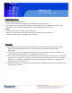
Front Panel Extend I/O Ports Power & HDD Led.
1-3 System Block Diagram FES 2215
1-4 Mechanical Diagrams FES 2215
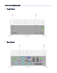
1-5 Front & Rear panel Front Panel Rear Panel
2-1 Front panel Pin Definition 1. Power On/ Off Button 2. Power Reset Button 3.
2. COM 1 (DB-9): RS-232/ 422/ 485 [refer to P.17-18, No. 8 jumper setting] PIN RS-232 RS-422 RS-486 1 DCD# TX+ RTX+ 2 RXD RX+ Not Used 3 TXD TX- RTX- 4 DTR# RX- Not Used 5 GND GND GND 6 DSR# Not Used Not Used 7 RTS# Not Used Not Used 8 CTS# Not Used Not Used 9 RI# Not Used Not Used 4 & 5. LAN 1 & 2 (RJ-45) 6.
2-3 Internal Pin Definition & Jumper Settings 2-3.
2-3.
2-3.3 Jumper Settings 1. Clear CMONS Jumper (CLRCMOS1) [refer to P.13, No. 16] It allows you to clear the data in CMOS. To clear and reset the system parameters to default setup, please turn off the computer and unplug the power cord from the power supply. After waiting for 15 seconds, use a jumper cap to short pin 2 and pin 3 on CLRCMOS1 for 5 seconds. However, please do not clear the CMOS right after you update the BIOS.
7. Panel Resolution Selection (12-pin JLVD_GPIO1) [refer to P.13, No. 29] 8. SET COM Ports (10-pin SET_CM1,2) [refer to P.13, No. 1] (10-pin SET_CM4,5,6) [refer to P.13, No. 20] (5-pin SET_CM3) [refer to P.13, No.
(COM 1 Pin1 & Pin 9 Function Setting) Item Pin 1 Function Connector SET_COM1 Jumper Setting Config. 1 Provide +12V Power Source Pin 1 & Pin 3 short, Pin 5 & 7 & 9 NC Config. 2 Provide +5V Power Source Pin 3 & Pin 5 short, Pin 1 & 3 & 9 NC Config. 3 Provide DCD# Function Pin 7 & Pin 9 short, Pin 1 & 3 & 5 NC Item Pin 9 Function Connector SET_COM1 Jumper Setting Config. 1 Provide +12V Power Source Pin 2 & Pin 4 short, Pin 6 & 8 & 10 NC Config.
10. USB 2.0 Ports (4-pin USB 4,5) [refer to P.13, No. 11] (4-pin USB6) [refer to P.13, No. 12] 11. System Panel Header (9-pin PANEL 1) [refer to P. 13, No. 15] Connect the power switch, reset switch and system status indicator on the chassis to this header according to the pin assignments below. Note the positive and negative pins before connecting the cables.
13. Front Panel Audio Header (9-pin HD_AUDIO1) [refer to P.13, No. 25] 14. DC 12V Power Connector (4-pin DC 12V1) [refer to P.13, No. 3] 15. COM Port 4,5,6 (10-pin COM 4,5,6) [refer to P. 13, No.
16. Print Port Header (25-pin LPT1) [refer to P.13, No. 9] 17. LVDS Con (40-pin LVDS1) [refer to P.13, No. 2] 18. Output Power (4-pin SATA_PWR1) [refer to P.13, No.
19. Digital I/O Header (10-pin JGPIO1) [refer to P.13, No. 13] 20. Panel Brightness and Speaker Volume Control (7-pin BLT_VOL1) [refer to P.13, No. 21] 21. Panel BackLight Inverter Connector (6-pin BLT_PWR2) [refer to P.13, No. 22] 22. RJ-45 COM Port C (8-pin COM Port C ) [refer to P.13, No.
Chapter 3: UEFI Setup Utility 3-1 Introduction This section explains how to use the UEFI SETUP UTILITY to configure yours system. The UEFI chip on the motherboard stores the UEFI SETUP UTILITY. You may run the UEFI SETUP UTILITY when you start up the computer. Please press or during the Power-On-Self-Test (POST) to enter the UEFI SETUP UTILITY, otherwise, POST will continue with its test routines.
3-2 Main Screen When you enter the UEFI SETUP UTILITY, the Main screen will appear and display the system overview.
3-3 Advanced Screen In this section, you may set the configurations for the following items: CPU Configuration, Chipset Configuration, Storage Configuration, Super IO Configuration, ACPI Configuration, USB Configuration and Voltage Configuration. Setting wrong values in this sectio may cuase the system to malfunction. Instant Flash Instant Flash is a UEFI flash utility embedded in Flash ROM.
3-3.1 CPU Configuration Intel Hyper Threading Technology To enable this feature, it requires a computer system with an Intel processor that supports HyperThreading technology and an operating system that includes optimization for this technology, such as Microsoft® Windows®7. Set to [Enabled] if using Microsoft® Windows®7. No-Execute Memory Protec tion No-Execution (NX) Memory Protection Technology is an enhancement to the IA-32 Intel Architecture.
3-3.2 Chipset Configuration Set Panel Type by Use this to configure Set Panel Type.The Default value is [UEFI Setup]. Panel Type Selection Use this to select panel type. The default value is [1366x768/ 18-bit/ 1-ch/LED ]. ACPI HPET Table Use this item to enable or disable ACPI HPET Table. The default value is [Enabled]. Please set this option to [Enabled] if you plan to use this motherboard to submit W indows® certification.
3-3.3 Storage Configuration Onboard SATAII Mode Use this to select SATA 2 mode. The default value is [IDE Mode]. Configuration options: [IDE Mode], [AHCI Mode] and [D isabled]. ACHI (Advanced Host Controller Interface) supports NCQ and other new features that will improve SATA disk performance but IDE mode does not have these advantage. Hard Disk S.M.A.R.T Use this item to enable or disable the S.M.A.R.T (Self-Monitoring, Analysis, and Reporting Technology) feature.
3-3.4 Super IO Configuration COM 1 Configuration Use this to set parameters of COM1. COM 2 Configuration Use this to set parameters of COM2. COM 3 Configuration Use this to set parameters of COM3. COM 4 Configuration Use this to set parameters of COM4. COM 5 Configuration Use this to set parameters of COM5. COM 6 Configuration Use this to set parameters of COM6. LPT1 Configuration Use this to set parameters of the onboard parallel port.
3-3.5 ACPI Configuration Suspend to RAM Use this item to select whether to auto-detect or disable the Suspend-to-RAM feature. Select [Auto] will enable this feature if the OS supports it. S3 Video Repost Use this to enable/disable S3 Video Repost. The default value is [Enabled]. PS/2 Keyboard Power On Use this item to enable or disable PS/2 keyboard to turn on the system from the power-soft-off mode.
3-3.6 USB Configuration USB 2.0 Controller Use this item to enable or disable the use of USB 2.0 controller. Legacy USB Support Use this option to select legacy support for USB devices. There are four configuration options: [Enabled], [Auto], [Disabled] and [UEFI Setup Only]. The default value is [Enabled]. Please refer to below descriptions for the details of these four options: [Enabled]: Enables support for legacy USB. [Auto]: Enables legacy support if USB devices are connected.
3-3.7 Voltage Configuration DRMA Voltage Use this item to select DRMA Voltage. The default value is [Auto].
3-4 Hardware Health Event Monitoring Screen In this section, it allows you to monitor the status of the hardware on your system, including the parameters of the CPU temperature, motherboard temperature, CPU fan speed, chassis fan speed, and the critical voltage. CPU_FAN 1 Setting This allows you to set CPU-FAN 1’s speed. Configuration options: The default value is [Full On]. [Full On] and [Automatic Mode]. CHA_FAN 1 Setting This allows you to set CHA-FAN 1’s speed.
3-5 Boot Screen In this section, it will display the available devices on your system for you to configure the boot settings and the boot priority. Setup Prompt Timeout This shows the number of seconds to wait for setup activation key. 65535 (0XFFFF) means indefinite wa iting. Bootup Num-Lock If this item is set to [On], it will automatically activate the Numeric Lock function after boot-up. Boot From Onboard LAN Use this item to enable or disable the Boot From Onboard LAN feature.
3-6 Security Screen In this section, you may set, change or clear the supervisor/ user password for the system.
3-7 Exit Screen Save Changes and Exit When you select this optino, it will pop-out the following message, “Save configuration changes and exit setup?” Select [OK] to save the changes and exit the UEFI SETUP UTILITY. Discard Changes and Exit When you select this option, it will pop-out the following message, “Discard changes and exit setup? ” Select [OK] to exit the UEFI SETUP UTILITY without saving any changes.
Chapter 4: Installation Guide 4-1. Memory Modules (SO-DIMM) Pipal 2215 provides two 240-pin DDR3 SO-DIMM slots. - It is NOT allowed to install a DDR or DDR2 memory module into a DDR 3 slot; otherwise, the motherboard and SO-DIMM may be damaged. - Please install the memory module from DDR3_A2 slot as the 1st priority. 4-1.1 Installing a SO-DIMM Please make sure to disconnect the power supply before adding or removing SO-DIMMs or the system components.
4-2. Expansion Slot (PCI Slot) There is 1 Mini-PCI-E expansion slot for FES 2215. PCI Slot: The PCI slot is used to install an expansion card that has 32-bit PCI interface. 4-2.1 Installing an expansion card STEP 1: Before installing the expansion card, please make sure that the power supply is switched off or the power cord is unplugged. Please read the documentation of the expansion card and make necessary hardware setting for the card before you start the installation.