FES2953 Fanless Embedded System User Manual FES2953: Fanless Embedded System Core i7 2.66GHz/ Core i5 2.4GHz Processor 14628 Central Ave, Chino, CA 91710 tel:909.597.7588, fax:909.597.1939 © Copyright 2013 Acnodes, Inc. All rights reserved. Product description and product specifications are subject to change without notice. For latest product information, please visit Acnodes’ web site at www.acnodes.com.
FES2953 Fanless Embedded System Table of Contents Accessories.............................................................................................................. 3 Components............................................................................................................ 4 Front V iew ..................................................................................................................... 4 Rear V iew …………………….................................................................
Safety Information FES2953 is designed and tested to meet the latest standards of safety for information technology equipment. However, to ensure your safety, it is important that you read the following safety instructions. Setting up your system Read and follow all instructions in the documentation before you operate your system. Do not use this product near water. Set up the system on a stable surface or secure on wall with the provided rail.
The system was dropped or the cabinet is damaged. Lithium-Ion B attery Warning CAUTIO N: Danger of explosion if battery is incorrectly replaced. Replace only with the same or equivalent type recommended by the manufacturer. Dispose of used batteries according to the manufacturer’s instructions.
Accessories a. Power Cord x 1 b. M/B Manual x 1 c. Driver CD x 1 d. Power Brick x 1 e. Mounting Rail Screw x 6 f.
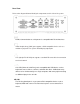
Components Front V iew Refer to the diagram below to identify the components on this side of the system. PWR The power LED illuminated when system been power on. HDD The hard disk LED blinks when data is being written into or read from the hard disk drive. RST The reset switch allows reset the system. ON/OFF The power switch allows powering O N and OFF the system. USB The USB (Universal Serial Bus) port is compatible with USB devices such as keyboards, mouse devices, cameras, and hard disk drives.
Rear Vie w Refer to the diagram below to identify the components on this side of the system. CO M1, Communication or serial port one is compatible with RS-232 interface. Video Graphic Array (VGA) port supports a VGA-compatible device such as a monitor or projector. The system default display output port. The eight-pin RJ-45 LAN port supports a standard Ethernet cable for connection to a local network.
DVI-D / DVI-I The Digital Visual Interface (DVI) port supports a high quality VGA-compatible device such as a monitor or projector to allow viewing on a larger external display. DVI-D only contain digital TMDS signal without analog VGA compatible single in it. The stereo headphone jack (3. 5mm) is used to connect the audio signal into system to record or bypass it to storage or LINE OUT. The stereo audio jack (3.5mm) is used to connect the system’s audio out signal to amplified speakers or headphones.
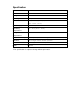
Specification Construction Alu minum Chassis C olor Silver Storage 2.5” 80GB SATA HDD x 1 Mounting Desktop or wall mount Dimensions 199(W) x 63. 4(H) x 232( D)mm (7.83” x 2.50” x 9.13” ) Power Supply 80W DC adapter Operating 0°C ~ 45°C (32 °F ~ 113°F) Temperature Storage -20°C ~ 80°C Temperature Relative Humidity 5~95% @45°C (non -con densing) Vibration HDD: 0.
Mounting FES2953 to the Wall Using attached mounting rail, you can install FES2953 on wood, drywall surface over studs, or a solid concrete or metal plane. Ensure the installer uses at least four M4 length 8mm screws to secure the system on wall. Six M4 length 8mm screws are recommended to secure the system on wall. Fasteners are not included with the unit, and must be supplied by the installer. The types of fasteners required are dependent on the type of wall construction.
routing. And have good ventilation for power adapter. The method of mounting must be able to support weight of the FES2953 plus the suspend weight of all the cables to be attached to the system. Use the following methods for mounting your system: Mounting to hollow w alls Method 1: Wood surface – A minimum wood thickness – 38mm (1.5in.) by 25.4 cm (10in.) – of high, construction – grade wood is recommended.
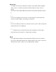
Exploded view of the FES2953 assembly
Parts description Part NO. Description Part NO.
D RI V ERS INSTALLATION D rivers Installation T hi s section de sc ri bes t he instal lati on procedures for software a nd drivers under the W indows 2000 a nd W indows X P . The software a nd drivers a re i nc luded with the motherboard. If you find the ite ms missing, ple ase c ont act the vendor w here you made the purchase. The contents of thi s section include t he follow ing: Chipset S oft ware Installat ion Uti lit y.................................................... 13 V GA Drivers Installation ..
D R IV ER SINSTALLA TION Ch ip set S oftware Installa tio n Utility The Chipset D ri vers should be install ed first before the softwa re drivers t o e na ble P lug & P lay INF support for c hi pset c ompone nt s. Follow t he instructio ns below to comple te t he installation. 1. Insert the CD t ha t comes w ith the board. Cl ick Intel a nd t he n Intel(R) QM57 Chipset D ri vers. 2. Click Intel(R) Chipset S oftware Insta llatio n U tili ty. 3.
DRIVERSINSTALLATION 4. Click Yes to accept the software license agreement and proceed with the installation process. 5. On the Readme File Information screen, click Next to continue the installation. 6. The Setup process is now complete. computer and for changes to take effect.
D R IV E R S IN S TA L L A TI ON V G A D r iv ers I nst alla tion N O T E: B efo re in sta ll ing th e I nt el(R ) Q M5 7 C hi p set F a m i ly Gra p hics D riv er, th e M ic rosoft .N ET F ramewo rk 3 .5 SP I sh o ul d b e fir st in sta l led. To ins tall the V GA drive rs, foll o w the s tep s b elo w . 1 . Ins ert the C D t ha t comes w ith the b o ard . Click I ntel and t h en I nt el(R ) Q M5 7 C hip s et D r iver s . 2 . C lick I nt el(R ) QM 5 7 C hip s et F a m i ly G rap hi cs D r iver . 3 .
D R I V E R S IN ST A L L A T IO N 4 . Cl ick Y e s t o to a g r e e w i th t he li c e n s e a g r e e m e n t a n d c o n tinu e th e in s tal lati o n . 5 . O n t h e R e a d m e F ile In f o r m a t io n sc r e e n , c lic k N e x t t o c o n tinu e t h e in s tal lati o n of t he I n tel® G r a p h ics M e d ia A c c e ler a t o r D r iv e r . 6 . O n S e tu p P r o gr e ss sc r e e n , c li c k N e x t to c o n tinu e . 7 . Se tu p c o m p lete .
DRIVERSINSTALLATION Realtek HD Audio Driver Installation Follow the steps below to install the Realtek HD Audio Drivers. 1. Insert the CD that comes with the board. Click Intel and then Intel(R) QM57 Chipset Drivers. 2. Click Realtek High Definition Audio Driver. 3. On the W elco me to the InstallShield Wizard screen, click Next. 3. InstallShield W izard is complete. Click Finish to restart the computer.
D RI V E RS INST ALLAT ION LAN Driver s Installa tion Follow th e s teps be low to in stall the Inte l LAN dr ivers . 1. Insert t he CD t hat comes with the board. Click I nte l and t hen I n tel(R) Q M57 Chipset Driver s . 2. Click I nt el(R) PRO L AN N etwork D ri ver. 3. When the Welcome s creen appea rs, cli ck Next. O n t he ne xt screen, cl ick Ye s to to a gre e wi th the l icens e agree me nt.
DRIVERSINSTALLATION 4. Click the checkbox for Drivers in the Setup Options screen to select it and click Next to continue. 5. The wizard is ready to begin installation. Click Install to begin the installation.
D RI V E RS INST ALLAT ION 6. When Instal lS hi eld Wi zard is complet e, clic k F i ni sh .
DR IV E R S IN S TALL ATI ON Ma nage me nt E ngine Int erf ace N O T E: B efor e ins ta lli ng th e I nte l(R ) A M T 6 .0 Dr ive rs , the M ic ro so ft .N ET Fr a mew o rk 3 .5 SPI sh o uld be first ins ta lle d. Foll o w th e ste ps belo w to in stall the I ntel M a nag e men t E ngin e. 1 . In sert th e d rive rs d is c th at co m es wit h th e m o th erbo ard. C li ck In tel and th en I nt el(R) A MT 6 .0 D ri ver s.
D RI V ERS INSTALLATION 2. W hen the Wel come scree n to t he InstallShield Wi zard for Inte l® M anageme nt Engine Components, c lick Next. On the ne xt scree n, cli ck Ye s to t o a gree with the l icense agreeme nt. 2. W he n the Setup Progress screen a ppe ars, clic k Next. T hen, cli ck Finish when the setup progress has be en suc cessfull y i nst alle d.
D R IV ER SINSTALLA TION
BI OS SETUP BIOS Setup T hi s c ha pter describes the different set tings available i n the BIOS that co me s with t he board. The t opics covered i n this chapter are as follo ws: BIOS Introductio n ........................................................................................ 25 BIOS Setup .................................................................................................... 2 5 Main BIOS Se tup ......................................................................................
B IO S S E T U P B I O S I n tro d u c tio n T h e B I OS (Ba si c I n p u t/O u tp u t S y s te m ) in s ta ll e d i n y o u r c o m pu t e r s y ste m ’ s R O M su p p o r ts I n te l p ro c e ss o r s. T h e B I O S pr o v id e s c r itic a l lo w - le v e l s u p po r t f o r a s ta n d a r d d e v ic e s u c h a s d is k d r i ve s, s e r ia l p o r ts a n d p a r a lle l p o r ts .
B IO S S E T U P M a i n B I O S S e tu p Th is se tup allo ws yo u t o re cord some b asic ha rdware c on fi gu ration s in y o ur c o mp ut er s yste m a nd s et t he s ystem c lock .
BIOS SETUP Advanced Settings This section allows you to configure and improve your system and allows you to set up some system features according to your preference.
BIO S SETUP PCI Subsystem Settings This section allo ws you to configure the PCI, PCI-X and PCI Express settings. Ap tio Setu p Ut ilit y Main Advanced PCI Bus Dr iv er Vers ion PCI RO M Pri ority Chipset Bo ot V 2.02.
BI O S S E T U P ACP I S ettin gs A ptio Set up U t ility M a in Ad v a n c e d E n a bl e H i b e rna tion A C PI S l e e p Sta te C h ipse t B oo t Sec urity S a ve & Exit Ena b l e d S 3 (S u s p e n d to R … ) → ←Select Screen Select Item Enter: Select + - Ch a n g e F i e l d F 1 : Ge n e r a l H e l p F 2 : Pr e v i o u s V a l u e s F 3 : O p t i m i z e d D ef a u l t ↑↓ F4: Save E S C : Ex i t En able H ibe rn ation En ab les o r D isables S yste m a bility to Hib er nate (O S /S4 S leep S t
B IO S S E T UP Wake up event s e ttings Apt io S etup Utility M ain Ad van ced Chipset W ak e sy stem with Fi xed Ti m e W ak e up hour W ak e up mi nute W ak e up sec ond W ak e on Ring W ak e on PME Bo ot Di sabl ed 0 0 0 E nabled E nabled Securit y S ave & Exit → ← Select Screen Select Item Enter: Select +- Change Field ↑↓ F1: General Help F2: Previous Value s F3: Optimize d Default F4: Save ESC: Exit Wake system wi th Fixed Ti me En ab les or D isab les System wake o n alarm ev ent.
BI O S S E T U P C P U C o n f ig u r a t i o n T h i s s e c t i o n s h o w s t h e C P U c o n fi g u r a t i o n p a r a m e t e r s .
B IO S S E T U P Adj acen t Cach e L ine P refetc h To tu rn o n/of f pr ef etchin g of a djac en t c a ch e lines. Inte l V i rtua liz a tion Tec hnology W hen en ab led , a V MM c an utiliz e the a dd itio nal har dw ar e c ap ab ilities pr ovid ed by V a nder poo l T ec hn olog y. P ow er Tech nolog y En ab le the powe r m a nageme nt fe a tures. TD C L im i t / TD P Limit Tu rb o-XE Mod e P roce ssor TD C L imit in 1 /8 A granu larity. 0 m ea n s usin g the fa c tor y-con fig ured value.
BI O S S E T U P Inte l IG D S W S C I O p Re g ion A pt io S e tup U tilit y M a in Ad v a n c e d C h ips e t In te l IG D SW SC I OpR e g io n C o n fi g u ra ti on B oo t D V MT /FIXE D Me mor y 256M B IGD – B o o t Ty p e A cti ve L FP V B IOS D e fa u l t N o L V D S P ane l C o l or D e p th L FP L C D P a n e l T ype 18 B it 1 0 2 4 x 7 6 8 LV D S P a n el S cal in g A u to Sec urity S a ve & Exit → ←Select Screen Select Item Enter: Select ↑↓ +F1: F2: F3: Ch a n g e F i e l d Ge n e r
B IO S SETUP USB Co nfiguration Apt io S etup Utility M ain Ad van ced US B Configur ati on Chipset Bo ot Secu rit y S ave & Exit → ← Select Screen US B Devi ces : 2 Hubs Legac y US B S upport Select Item Enter: Select +- Change Field ↑↓ Enabl ed F1: General Help E HCI Hand-off E nabled Dev ic e Reset T im eout 20 s ec F2: Previous Values F3: Optimized Default F4: Save ESC: Exit Legacy U SB Su pport En ab les L eg acy USB supp ort.
BIOS SETUP Super IO Configuration Aptio Set up Ut ility Main Advanced Super IO Configuration Ch ipset Boo t Security Save & Exit → ← Select Screen Super IO Chip -> Serial Por t 0 C onfiguration F intek F81865 -> Serial Por t 1 C onfiguration -> Serial Por t 2 C onfiguration Select Item Enter: Select +- Change Field ↑↓ F1: General Help -> Serial Por t 3 C onfiguration Power Failur e Power ON F unction Alway s off Disabled ACPI Shutdown Temperatur e Disabled F2: Previous Values F3: Optimized Def
BIOS SETUP H/W Monitor Apt io Setup Utilit y Main Advance d PC Health Status Chipset Boo t Secu rit y Save & Exit System Temperatur e1 System Temperatur e 2 + 51 C + 35 C System FAN1 Speed System FAN2 Speed N /A 7109 RPM → ← Select Screen VCC3V + 3.408 V ↑↓ Vin0 Vin2 + 0.928 V + 5.087 V Vin3 VSB3V + 12.232 V + 3.424 V VBAT Fan1 Smart F an Control + 3.
BI OS SETUP AMT C onfiguration Apt io S etup Utilit y Ad van ced M ain Chip set A MT Bo ot S ecurity Save & E xit E nabled → ← Select Screen Select Item Enter: Select +- Change Field F1: General Help ↑↓ F2: Previous Values F3: Optimized Default F4: Save ESC: Exit AMT Options are Enabled and Disabled .
BI OS SETUP C hipset Settings T hi s sec tion a llows you to c onfi gure and i mprove your system and al lows you to set up some syst em feat ure s acc ording t o your preference . Aptio Set up Ut ility Main Ad van ced Ch ipset Bo ot Secu rit y S ave & Exit ? Nor th Br idge ? S outh Br idge → ← Select Screen ? ME Subs ys tem ↑↓ Select Item Enter: Select +- Change Field F1: General Help F2: Previous Values F3: Optimized Default F4: Save North Bridge This item sh ows th e North Brid ge Parameters.
BI O S S E T U P North B ri dge This section allo ws you to configure t he North B ridge C hipset.
BIOS SETUP PCI Express Port Options are Disabled, Enabled and Auto. IGD Memory IGD Share Memory Size. Options are Disable, 32M, 64M and 128M. PAVP Mode Select PAVP Mode usedby Internal Graphics Device. Options are Disabled and Enabled. PEG Force Gen1 PCI Express Port Force Gen1.
B IOS SETU P SB C hip set Co nfigu ration This se ction al lows you t o confi gure the So ut h Bri dge Chipset.
B IO S S E T U P B o o t Se ttin g s Th is se ctio n al lows y o u to con figu re the b o o t s ett ing s ac cording to yo ur p referen ce . Ap tio S e tu p U t ilit y M a in Ad v a nc e d C hips e t B o ot Se c u rit y B o o t C o n fig u r a ti o n Q u ie t B o o t D i s a bl e d F a st B o o t D i sa b l e d S e tu p Pr o mpt T i me o u t B o o tu p N u mLo c k S ta te 1 On C S M 1 6 M o d ul e V e rs io n G a te A2 0 A cti ve 0 7 .
BIOS SETUP Boot Option Priorities Sets the system boot order. Hard Drive BBS Priorities Set the order of the legacy devices in this group. Security Settings This section allows you to configure and improve your system and allows you to set up some system features according to your preference.
B IO S SETUP Save & Exit Settings Ap tio S etu p Ut ilit y M ain Ad van ced Chipset Bo ot Secu rit y S ave & Exit S ave Changes and E xi t Di s ac ard Changes and E xi t S ave Changes and R es et Di s card Changes and Res et → ← Select Screen ↑↓Select Item Enter: Select S ave Changes Di s card Changes Res tore Defaul ts S ave as User Defaults Res tore Us er Defaul ts B oot Ov erri de S A TA : AT AP I i HDS116 4 S A TA : Hitac hi H DS721616P LA380 Launch EF I Shell fr om fi l esy stem device S av
BIOS SETUP Save as User Defaults Save the changes done so far as User Defaults. Restore User Defaults Restore the User Defaults to all the setup options. Boot Override Pressing ENTERcauses the system to enter the OS. Launch EFI Shell fromfilesystem device Attempts to Launch EFI Shell application (Shellx64.efi) from one of the available filesystem devices. Reset System with ME disable Mode ME will run into the temporary disable mode.