FPC 7160 15.6” Industrial Panel PC User Manual FPC 7160: 15.6” Industrial Panel PC with Intel Atom N270 processor 661 Brea Canyon Rd., Suite 3 Walnut, CA 91789 tel: 909.598.7388, fax: 909.598.0218 © Copyright 2011 Acnodes, Inc. All rights reserved. Product description and product specifications are subject to change without notice. For latest product information, please visit Acnodes’ web site at www.acnodes.com.
FPC 7160 15.6” Industrial Panel PC COPYRIGHT NOTICE The information in this document is subject to change without prior notice in order to improve reliability, design and function and does not represent a commitment on the part of the manufacturer. In no event will the manufacturer be liable for direct, indirect, special, incidental, or consequential damages arising out of the use or inability to use the product or documentation, even if advised of the possibility of such damages.
FPC 7160 15.6” Industrial Panel PC Table of Contents CHAPTER 1 INTRODUCTION 1.1 OVERVIEW ....................................................................................................................... 2 1.2 MODEL VARIATIONS ....................................................................................................... 3 1.3 FEATURES ....................................................................................................................... 3 1.4 EXTERNAL OVERVIEW ................
FPC 7160 15.6” Industrial Panel PC 2.7.8 COM3 TX FUNCTION SELECT JUMPER ..................................................... 34 2.7.8.1 COM3 RS-422 AND RS-485 PINOUTS ........................................... 35 2.8 MOUNTING THE SYSTEM ............................................................................................ 36 2.8.1 MONITOR STAND ............................................................................................ 37 2.8.2 CABINET AND RACK ......................................
FPC 7160 15.6” Industrial Panel PC 3.2 MAIN .............................................................................................................................. 58 3.3 ADVANCED ...................................................................................................................59 3.3.1 CPU CONFIGURATION ................................................................................... 60 3.3.2 IDE CONFIGURATION ........................................................................
FPC 7160 15.6” Industrial Panel PC CHAPTER 4 SYSTEM MAINTENANCE 4.1 SYSTEM MAINTENANCE INTRODUCTION .................................................................100 4.2 MOTHERBOARD REPLACEMENT ..............................................................................101 4.3 COVER REMOVAL ........................................................................................................101 4.4 MEMORY MODULE REPLACEMENT ..........................................................................
FPC 7160 15.6” Industrial Panel PC B.4.2 BACKUP SYSTEM .......................................................................................... 131 B.4.3 RESTORE YOUR LAST BACKUP ..................................................................132 B.4.4 MANUAL ...........................................................................................................133 B.5 OTHER INFORMATION ..................................................................................................134 B.5.
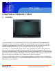
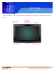
FPC 7160 15.6” Industrial Panel PC CHAPTER 1 INTRODUCTION 1.1 OVERVIEW The fanless panel PCs are all-in-one panel PCs with all the elements of a desktop computer contained in a single, slim package, no bigger than a thick monitor. The fanless panel PCs can be mounted on a desktop monitor stand and save a huge amount of desktop space by including all the computer components behind the screen. All models include a touch screen interface.
FPC 7160 15.6” Industrial Panel PC 1.2 MODEL VARIATIONS 15.6” FPC 7160 CPU: 1.6GHz Intel Atom Processor N270 15.6” FPC7162 CPU: 1.6GHz AMD ASB1 dual core L325 1.3 FEATURES Some of the standard features of the FPC7160/ FPC7162 flat panel PC include: Fully self-contained, only power from the external power supply required Touch screen Wireless LAN Gigabit Ethernet Bluetooth IP 64 protection RoHS compliant 1.
FPC 7160 15.6” Industrial Panel PC 1.4.1 FRONT PANEL The front side of the FPC 7160/ FPC7162 is a flat panel TFT LCD screen surrounded by a plastic frame. 661 Brea Canyon Rd., Suite 3 Walnut, CA 91789 tel: 909.598.7388, fax: 909.598.0218 © Copyright 2011 Acnodes, Inc. All rights reserved. Product description and product specifications are subject to change without notice. For latest product information, please visit Acnodes’ web site at www.acnodes.com.
FPC 7160 15.6” Industrial Panel PC 1.4.2 REAR PANEL The rear panel provides access to retention screw holes that support the wall mounting. Refer to Figure 1-3. 661 Brea Canyon Rd., Suite 3 Walnut, CA 91789 tel: 909.598.7388, fax: 909.598.0218 © Copyright 2011 Acnodes, Inc. All rights reserved. Product description and product specifications are subject to change without notice. For latest product information, please visit Acnodes’ web site at www.acnodes.com.
FPC 7160 15.6” Industrial Panel PC 1.4.3 BOTTOM PANEL The bottom panel has the following slots, buttons and switches (Figure 1-5): 1 x RJ-45 jack for Gigabit LAN 1 x Audio Line-out jack 1 x OSD keypad 1 x Power switch 1 x Power input (12 V) 1 x Reset button 1 x RS-232 serial port (COM1) 1 x RS-232/422/485 serial port (COM3) 4 x USB ports (AFL2-W15A-L325) 2 x USB ports (AFL2-W15A-N270) 1 x External SATA port (AFL2-W15A-N270) 1 x HDMI (AFL2-W15A-L325) 1 x VGA port 661 Brea Canyon Rd.
FPC 7160 15.6” Industrial Panel PC 1.5 INTERNAL OVERVIEW All the components are contained under the rear panel. The internal components include the touch panel module and the motherboard. The motherboard has memory, a wireless module, a SATA hard drive bay, and three expansion interfaces. Optionally, an HSDPA module can be installed in any of the models. 1.6 SPECIFICATIONS SPECIFICATIONS FPC 7160 FPC 7162 CPU: 1.6 GHz Intel® Atom processor N270/ 1.
FPC 7160 15.6” Industrial Panel PC I/O: FPC 7160 FPC 7162 1 x Gigabit LAN 1 x Gigabit LAN 1 x Audio line-out 1 x Audio line-out 1 x Power input (12 V) 1 x Power input (12 V) 1 x RS-232 1 x RS-232 1 x RS-232/422/485 1 x RS-232/422/485 2 x USB ports 4 x USB ports 1 x VGA port 1 x VGA port 1 x External SATA 1 x HDMI 1 x Power Button 1 x Power Button 1 x Reset Button 1 x Reset Button Expansion Interface: 2 x Type A module (PCIe x 1 + USB 2.
FPC 7160 15.6” Industrial Panel PC Power Consumption: 60 W 84W 90-246 VAC input 50/60 Hz 90-246 VAC input 50/60 Hz 12 V DC output 12 V DC output Power Consumption: 51W 68W Mounting Feature: VESA 100 mm x 100 mm Operaing Temperature-10ºC ~ 50ºC Dimension (W x H x D): 400 mm x 67 mm x54 mm Net/ Gross Weight: 3.8 kg Front Panel Protection: IP64 compliant EMC and Safety: CE, FCC, CB, CCC 661 Brea Canyon Rd., Suite 3 Walnut, CA 91789 tel: 909.598.7388, fax: 909.598.0218 © Copyright 2011 Acnodes, Inc.
FPC 7160 15.6” Industrial Panel PC 1.7 DIMENSIONS Width: 400 mm; Height: 267 mm; Depth: 54 mm 661 Brea Canyon Rd., Suite 3 Walnut, CA 91789 tel: 909.598.7388, fax: 909.598.0218 © Copyright 2011 Acnodes, Inc. All rights reserved. Product description and product specifications are subject to change without notice. For latest product information, please visit Acnodes’ web site at www.acnodes.com.
FPC 7160 15.6” Industrial Panel PC CHAPTER 2 INSTALLATION WARNING: When installing the FPC7160/ FPC7162, make sure to: -Turn the power off: Chance of electrocution. Turn off the monitor and unplug it from the power supply. -Only let certified engineers change the hardware settings: Incorrect settings can cause irreparable damage to the product. -Install the monitor with assistance: The product is very heavy and may be damaged by drops and bumps. Two or more people should install the panel PC.
FPC 7160 15.6” Industrial Panel PC 2.1 UNPACK THE PANEL PC To unpack the flat panel PC, follow the steps below: WARNING! Only remove the protective plastic cover stuck to the front screen after installation. The plastic layer protects the monitor surface during installation process. Step 1: Carefully cut the tape sealing the box. Only cut deep enough to break the tape. Step 2: Open the outside box. Step 3: Carefully cut the tape sealing the box. Only cut deep enough to break the tape.
FPC 7160 15.6” Industrial Panel PC 2.3 HARD DRIVE INSTALLATION This section outlines the installation of the hard drive in the FPC7160/ FPC7162. To install the hard drive, please follow the steps below: Step 1: Unfasten the right plastic side access panel (SATA/CF card/USB dongle access panel) retention screws and remove the right plastic side access panel (See figure below). Step 2: Locate the HDD/CF card brackets. Unfasten screws and removed brackets (See figure below). 661 Brea Canyon Rd.
FPC 7160 15.6” Industrial Panel PC Step 3: Insert the SATA connector end of the HDD into the bracket to connect the motherboard SATA connector to the hard drive SATA connector as shown in the figure below. Step 4: Replace the brackets, covers and screws. 2.4 COMPACTFLASH INSTALLATION The installation for a CompactFlash® card is described in this section. 2.4.1 COMPACTFLASH INSTALLATION Step 1: Remove the access panel and brackets as described in the HDD installation instructions.
FPC 7160 15.6” Industrial Panel PC Step 3: Install the CompactFlash® card into the slot (see figure below). 661 Brea Canyon Rd., Suite 3 Walnut, CA 91789 tel: 909.598.7388, fax: 909.598.0218 © Copyright 2011 Acnodes, Inc. All rights reserved. Product description and product specifications are subject to change without notice. For latest product information, please visit Acnodes’ web site at www.acnodes.com.
FPC 7160 15.6” Industrial Panel PC Step 4: Replace the brackets, access panel and screws. 2.5 EXPANSION MODULE INSTALLATION This section outlines the installation of the expansion modules in the FPC7160/ FPC7162. To install the modules, please follow the steps below: Step 1: Unfasten the left plastic side access panel (Expansion module access panel) retention screws and remove the left plastic side access panel (See figure below). Step 2: Locate the two bracket retention screws.
FPC 7160 15.6” Industrial Panel PC Step 3: Insert the expansion module connector end of the expansion module into the motherboard module connector to connect the module (See above). Step 4: Fasten the expansion module retention screws. Step 5: Replace the brackets, cover and screws. 661 Brea Canyon Rd., Suite 3 Walnut, CA 91789 tel: 909.598.7388, fax: 909.598.0218 © Copyright 2011 Acnodes, Inc. All rights reserved. Product description and product specifications are subject to change without notice.
FPC 7160 15.6” Industrial Panel PC 2.5.1 EXPANSION MODULE SLOT PINOUTS There are three connector for two kinds of expansion modules, Type A module and Type B module. Slot 1 and Slot 2 are for installing Type A module and Slot 3 is for Type B module. The pinouts of these slots are listed below. 661 Brea Canyon Rd., Suite 3 Walnut, CA 91789 tel: 909.598.7388, fax: 909.598.0218 © Copyright 2011 Acnodes, Inc. All rights reserved.
FPC 7160 15.6” Industrial Panel PC For the dimensions of the Type A and Type B expansion modules, please refer to Appendix C. 661 Brea Canyon Rd., Suite 3 Walnut, CA 91789 tel: 909.598.7388, fax: 909.598.0218 © Copyright 2011 Acnodes, Inc. All rights reserved. Product description and product specifications are subject to change without notice. For latest product information, please visit Acnodes’ web site at www.acnodes.com.
FPC 7160 15.6” Industrial Panel PC 2.6 USB DONGLE INSTALLATION (FPC7160 ONLY) The installation for an USB dongle is described in this section. Step 1: Remove the access panel and brackets as described in the HDD installation instructions. Step 2: Locate the USB dongle connector and install the USB dongle as shown below. Step 3: Replace the bracket, access panel and screws. 661 Brea Canyon Rd., Suite 3 Walnut, CA 91789 tel: 909.598.7388, fax: 909.598.0218 © Copyright 2011 Acnodes, Inc.
FPC 7160 15.6” Industrial Panel PC 2.7 JUMPER SETTINGS NOTE: A jumper is a metal bridge used to close an electrical circuit. It consists of two or three metal pins and a small metal clip (often protected by a plastic cover) that slides over the pins to connect them. To CLOSE/SHORT a jumper means connecting the pins of the jumper with the plastic clip and to OPEN a jumper means removing the plastic clip from a jumper. The following jumpers can be found on the motherboardinstalled in the FPC 7160/ FPC 7162.
FPC 7160 15.6” Industrial Panel PC 2.7.1 ACCESS THE JUMPERS To access the jumpers, please remove the back panel and the internal aluminum chassis. To remove the back panel, please refer to Section 4.3. 2.7.2 CF CARD SETUP Jumper Label: JCF1 (FPC7160) J2 (FPC7162) Jumper Type: 2-pin header Jumper Settings: See Table 2-6 Jumper Location: See Figure 2-9 The CF Card Setup jumper sets the CF Type I card or CF Type II cards as either the slave device or the master device.
FPC 7160 15.6” Industrial Panel PC The CF Card Setup jumper location is shown in Figure 2-9. 2.7.3 CLEAR CMOS JUMPER Jumper Label: J_CMOS1 Jumper Type: 3-pin header Jumper Settings: See Table 2-7 Jumper Location: See Figure 2-10 661 Brea Canyon Rd., Suite 3 Walnut, CA 91789 tel: 909.598.7388, fax: 909.598.0218 © Copyright 2011 Acnodes, Inc. All rights reserved. Product description and product specifications are subject to change without notice.
FPC 7160 15.6” Industrial Panel PC If the FPC7160/ FPC 7162 fails to boot due to improper BIOS settings, the clear CMOS jumper clears the CMOS data and resets the system BIOS information. To do this, use the jumper cap to close the pins for a few seconds then remove the jumper clip. If the "CMOS Settings Wrong" message is displayed during the boot up process, the fault may be corrected by pressing the F1 to enter the CMOS Setup menu.
FPC 7160 15.6” Industrial Panel PC 2.7.4 COM1 PORT PIN 9 SELECT Jumper Label: JP5 (FPC 7160) JP7 (FPC7162) Jumper Type: 10-pin header Jumper Settings: See Table 2-8 Jumper Location: See Figure 2-11 The jumper configures pin 9 on COM1 connector. Pin 9 on the COM1 connector can be set as the ring (RI) signal, +5 V or +12 V. The COM1 Pin 9 Setting jumper selection options are shown in Table 2-8. The COM1 Pin 9 Setting jumper locations are shown in Figure 2-11 below. 661 Brea Canyon Rd.
FPC 7160 15.6” Industrial Panel PC 661 Brea Canyon Rd., Suite 3 Walnut, CA 91789 tel: 909.598.7388, fax: 909.598.0218 © Copyright 2011 Acnodes, Inc. All rights reserved. Product description and product specifications are subject to change without notice. For latest product information, please visit Acnodes’ web site at www.acnodes.com.
FPC 7160 15.6” Industrial Panel PC 2.7.5 COM3 PORT PIN 9 SELECT Jumper Label: JP7 (FPC 7160) JP8 (FPC7162) Jumper Type: 6-pin header Jumper Settings: See Table 2-9 Jumper Location: See Figure 2-12 The jumper configures pin 9 on COM3 DB-9 connectors. Pin 9 on the COM3 DB-9 connector can be set as the ring (RI) signal, +5 V or +12 V. The COM3 Pin 9 Setting jumper selection options are shown in Table 2-8. The COM3 Pin 9 Setting jumper locations are shown in Figure 2-11 below. 661 Brea Canyon Rd.
FPC 7160 15.6” Industrial Panel PC 2.7.6 COM3 RX FUNCTION SELECT JUMPER Jumper Label: JP8 (FPC 7160) JP11 (FPC7162) Jumper Type: 8-pin header Jumper Settings: See Table 2-10 Jumper Location: See Figure 2-13 The COM3 RX Function Select jumper sets the communication protocol used by the RX serial communications port COM3 as RS-232, RS-422 or RS-485. The COM3 RX Function Select jumper settings are shown in Table 2-10. 661 Brea Canyon Rd., Suite 3 Walnut, CA 91789 tel: 909.598.7388, fax: 909.598.
FPC 7160 15.6” Industrial Panel PC The COM3 RX Function Select jumper location is shown in Figure 2-13. 661 Brea Canyon Rd., Suite 3 Walnut, CA 91789 tel: 909.598.7388, fax: 909.598.0218 © Copyright 2011 Acnodes, Inc. All rights reserved. Product description and product specifications are subject to change without notice. For latest product information, please visit Acnodes’ web site at www.acnodes.com.
FPC 7160 15.6” Industrial Panel PC 2.7.6 COM3 RX FUNCTION SELECT JUMPER Jumper Label: JP10 (FPC 7160) JP9 (FPC7162) Jumper Type: 12-pin header (four 3-pin headers combined) Jumper Settings: See Table 2-11 Jumper Location: See Figure 2-14 The COM3 RS-232/422/485 Serial Port Select jumper sets the communication protocol used by the second serial communications port (COM3) as RS-232, RS-422 or RS-485. The COM3 RS-232/422/ 485 Serial Port Select settings are shown in Table 2-11.
FPC 7160 15.6” Industrial Panel PC 2.7.8 COM3 TX FUNCTION SELECT JUMPER Jumper Label: JP11 (FPC 7160) JP10 (FPC7162) Jumper Type: 6-pin header Jumper Settings: See Table 2-12 Jumper Location: See Figure 2-15 The COM3 TX Function Select jumper configures the TX pin on COM3 serial port connector as RS-422 as an RS-485. The COM3 TX Function Select jumper selection options are shown in Table 212. The COM3 TX Function Select jumper location is shown in Figure 2-15 below. 661 Brea Canyon Rd.
FPC 7160 15.6” Industrial Panel PC 661 Brea Canyon Rd., Suite 3 Walnut, CA 91789 tel: 909.598.7388, fax: 909.598.0218 © Copyright 2011 Acnodes, Inc. All rights reserved. Product description and product specifications are subject to change without notice. For latest product information, please visit Acnodes’ web site at www.acnodes.com.
FPC 7160 15.6” Industrial Panel PC 2.7.8 COM3 RS-422 AND RS-485 PINOUTS The pinouts for RS-422 and RS-485 operation of external serial port COM 3 are detailed below. 2.8 MOUNTING THE SYSTEM WARNING! The panel PC is very heavy. Two or more people should mount the panel PC. Dropping or bumping the panel PC during installation can cause serious or irreparable damage to the panel PC. 2.8.1 MONITOR STAND The monitor stand allows the monitor to be used on a desk or table.
FPC 7160 15.6” Industrial Panel PC 2.8.2 CABINET AND RACK The FPC 7160/ FPC7162 flat panel PC can be installed into a cabinet or rack. The installation procedures are similar to the panel mounting installation. To do this, please follow the steps below: NOTE: When purchasing the cabinet/rack installation bracket, make sure it is compatible with both the FPC 7160/ FPC 7162 flat panel PC and the rack/cabinet into which the FPC 7160/ FPC 7162 is installed.
FPC 7160 15.6” Industrial Panel PC Step 4: Slide the flat panel PC with the attached rack/cabinet bracket into a rack or cabinet (Figure 219). Step 5: Once the flat panel PC with the attached rack/cabinet bracket has been properly inserted into the rack or cabinet, secure the front of the rack/cabinet bracket to the front of the rack or cabinet (Figure 2-19). 2.8.3 ARM MOUNTING The FPC7160/ FPC7162 can be installed on any arm that supports the standard VESA mounting interface.
FPC 7160 15.6” Industrial Panel PC To install the FPC7160/ FPC7162 on the arm, follow the directions below. NOTE: Make sure the arm supports standard VESA mounting. The FPC7160/ FPC 7162 uses a VESA mounting to attach to the arm. Step 1: The arm is purchased separately. Follow the instructions in the arm's user manual to securely attach the arm to the wall. Step 2: Once the mounting arm has been firmly attached to the surface, lift the flat panel PC onto the interface pad of the mounting arm.
FPC 7160 15.6” Industrial Panel PC Step 1: Select the location on the wall for the wall-mounting bracket. Step 2: Carefully mark the locations of the four brackets screw holes on the wall. Step 3: Drill four pilot holes at the marked locations on the wall for the bracket retention screws. Step 4: Align the wall-mounting bracket screw holes with the pilot holes. Step 5: Secure the mounting-bracket to the wall by inserting the retention screws into the four pilot holes and tightening them (Figure 2-23).
FPC 7160 15.6” Industrial Panel PC Step 6: Insert the four monitor mounting screws provided in the wall mounting kit into the four screw holes on the real panel of the flat panel PC and tighten until the screw shank is secured against the rear panel (Figure 2-24). Step 7: Align the mounting screws on the monitor rear panel with the mounting holes on the bracket.
FPC 7160 15.6” Industrial Panel PC 2.8.5 Panel Mounting To mount the panel PC into a panel, please follow the steps below. Step 1: Select the position on the panel to mount the flat panel PC. Step 2: Cut out a section corresponding to the size shown below. The size must be smaller then the outer edge. Recommended cutout sizes are shown below. 661 Brea Canyon Rd., Suite 3 Walnut, CA 91789 tel: 909.598.7388, fax: 909.598.0218 © Copyright 2011 Acnodes, Inc. All rights reserved.
FPC 7160 15.6” Industrial Panel PC Step 3: Slide the flat panel PC through the hole until the aluminum frame is flush against the panel. Step 4: Insert the panel mounting clamps into the pre-formed holes along the edges of the chassis, behind the aluminum frame. Step 5: Tighten the screws that pass through the panel mounting clamps until the plastic caps at the front of all the screws are firmly secured to the panel (Figure 2-27). 2.8.
FPC 7160 15.6” Industrial Panel PC Step 3: Slide the flat panel PC through the hole until the aluminum frame is flush against the panel. Step 4: Insert the panel mounting clamps into the pre-formed holes along the edges of the chassis, behind the aluminum frame. Step 5: Tighten the screws that pass through the panel mounting clamps until the plastic caps at the front of all the screws are firmly secured to the panel. 661 Brea Canyon Rd., Suite 3 Walnut, CA 91789 tel: 909.598.7388, fax: 909.598.
FPC 7160 15.6” Industrial Panel PC 2.9 Bottom Panel Connectors The bottom panel connectors extend the capabilities of the panel PC but are not essential for operation (except power). 2.9.1 LAN Connection The RJ-45 connectors enable connection to an external network. To connect a LAN cable with an RJ-45 connector, please follow the instructions below. Step 1: Locate the RJ-45 connector on the bottom panel of the FPC 7160/ FPC 7162. Step 2: Align the connectors.
FPC 7160 15.6” Industrial Panel PC Step 3: Insert the LAN cable RJ-45 connector. Once aligned, gently insert the LAN cable RJ-45 connector into the onboard RJ-45 port. 2.9.2 Serial Device Connection The serial device connectors are for connecting serial devices to the FPC 7160/ FPC7162. Follow the steps below to connect a serial device to the FPC 7160/ FPC7162 panel PC. Step 1: Locate the DB-9 connector. The location of the DB-9 connector is shown in Chapter 2. Step 2: Insert the serial connector.
FPC 7160 15.6” Industrial Panel PC Step 3: Secure the connector. Secure the serial device connector to the external interface by tightening the two retention screws on either side of the connector. 2.9.3 USB DEVICE CONNECTION To connect USB devices to the FPC7160/ FPC 7162, please follow the instructions below. Step 1: Located the USB connectors. The locations of the USB connectors are shown in Chapter 2. Step 2: Align the connectors.
FPC 7160 15.6” Industrial Panel PC Step 2: Align the VGA connector. Align the male DB-15 connector on the VGA screen cable with the female DB-15 connector on the external peripheral interface. Step 3: Insert the VGA connector Once the connectors are properly aligned with the insert the male connector from the VGA screen into the female connector on the FPC7160/ FPC7162. See Figure 235. Step 4: Secure the connector.
FPC 7160 15.6” Industrial Panel PC 2.11.2 RFID MODULE FOR MF MODEL Table 2-15 lists the specifications of the RFID module installed in the FPC7160/ FPC7162 MF models. 661 Brea Canyon Rd., Suite 3 Walnut, CA 91789 tel: 909.598.7388, fax: 909.598.0218 © Copyright 2011 Acnodes, Inc. All rights reserved. Product description and product specifications are subject to change without notice. For latest product information, please visit Acnodes’ web site at www.acnodes.com.
FPC 7160 15.6” Industrial Panel PC 2.11.3 SERIAL PORT (COM) SETTINGS The COM port settings have to be set correctly to enable the communication with the built-in RFID reader. Please follow the information below to setup the COM port settings. Step 1: Launch the Hyper Terminal from the Start menu (Start Programs Accessories Communications HyperTerminal). Step 2: Setup the port properties as shown below. Bits per second: 9600 Data bits: 8 Parity: None Stop bits: 1 Flow control: None 661 Brea Canyon Rd.
FPC 7160 15.6” Industrial Panel PC 2.12 DRIVER INSTALLATION NOTE: The content of the CD may vary throughout the life cycle of the product and is subject to change without prior notice. Visit the IEI website or contact technical support for the latest updates. The following drivers can be installed on the system.
FPC 7160 15.6” Industrial Panel PC CHAPTER 3 BIOS SETUP 3.1 Introduction The BIOS is programmed onto the BIOS chip. The BIOS setup program allows changes to certain system settings. This chapter outlines the options that can be changed. 3.1.1 Starting Setup The AMI BIOS is activated when the computer is turned on. The setup program can be activated in one of two ways. 1. Press the DELETE key as soon as the system is turned on or 2.
FPC 7160 15.6” Industrial Panel PC 3.1.3 Getting Help When F1 is pressed a small help window describing the appropriate keys to use and the possible selections for the highlighted item appears. To exit the Help Window press ESC or the F1 key again. 3.1.4 Unable to Reboot After Configuration Changes If the computer cannot boot after changes to the system configuration is made, CMOS defaults. Use the jumper described in Chapter 5. 3.1.
FPC 7160 15.6” Industrial Panel PC 3.2 Main The Main BIOS menu (BIOS Menu 1) appears when the BIOS Setup program is entered. The Main menu gives an overview of the basic system information. System Overview The System Overview lists a brief summary of different system components. The fields in System Overview cannot be changed.
FPC 7160 15.6” Industrial Panel PC -System Memory: Displays the auto-detected system memory. o Size: Lists memory size The System Overview field also has two user configurable fields: System Time [xx:xx:xx] Use the System Time option to set the system time. Manually enter the hours, minutes and seconds. System Date [xx/xx/xx] Use the System Date option to set the system date. Manually enter the day, month and year. 3.
FPC 7160 15.6” Industrial Panel PC 3.3.1 CPU Configuration Use the CPU Configuration menu (BIOS Menu 3) to view detailed CPU specifications and configure the CPU. 661 Brea Canyon Rd., Suite 3 Walnut, CA 91789 tel: 909.598.7388, fax: 909.598.0218 © Copyright 2011 Acnodes, Inc. All rights reserved. Product description and product specifications are subject to change without notice. For latest product information, please visit Acnodes’ web site at www.acnodes.com.
FPC 7160 15.6” Industrial Panel PC The CPU Configuration menu (BIOS Menu 3) lists the following CPU details: Manufacturer: Lists the name of the CPU manufacturer Brand String: Lists the brand name of the CPU being used Frequency: Lists the CPU processing speed FSB Speed: Lists the FSB speed Cache L1: Lists the CPU L1 cache size Cache L2: Lists the CPU L2 cache size 3.3.
FPC 7160 15.6” Industrial Panel PC ATA/IDE Configurations [Compatible] Use the ATA/IDE Configurations option to configure the ATA/IDE controller. Disabled Compatible Disables the on-board ATA/IDE controller. Configures the on-board ATA/IDE controller to be in compatible mode. In this mode, a SATA channel will replace one of the IDE channels. This mode sup ports up to 4 storage devices. Enhanced (DEFAULT) Configures the on-board ATA/IDE controller to be in Enhanced mode.
FPC 7160 15.6” Industrial Panel PC IDE Master and IDE Slave When entering setup, BIOS auto detects the presence of IDE devices. BIOS displays the status of the auto detected IDE devices. The following IDE devices are detected and are shown in the IDE Configuration menu: Primary IDE Master Primary IDE Slave Secondary IDE Master Secondary IDE Slave The IDE Configuration menu (BIOS Menu 4) allows changes to the configurations for the IDE devices installed in the system.
FPC 7160 15.6” Industrial Panel PC Auto-Detected Drive Parameters The "grayed-out" items in the left frame are IDE disk drive parameters automatically detected from the firmware of the selected IDE disk drive. The drive parameters are listed as follows: Device: Lists the device type (e.g. hard disk, CD-ROM etc.) Type: Indicates the type of devices a user can manually select Vendor: Lists the device manufacturer Size: List the storage capacity of the device.
FPC 7160 15.6” Industrial Panel PC Use the LBA/Large Mode option to disable or enable BIOS to auto detects LBA (Logical Block Addressing). LBA is a method of addressing data on a disk drive. In LBA mode, the maximum drive capacity is 137 GB. Disabled BIOS is prevented from using the LBA mode control on the specified channel. Auto DEFAULT BIOS auto detects the LBA mode control on the specified channel.
FPC 7160 15.6” Industrial Panel PC DMA Mode [Auto] Use the DMA Mode BIOS selection to adjust the DMA mode options. Auto DEFAULT BIOS auto detects the DMA mode. Use this value if the IDE disk drive support cannot be determined. SWDMA0 Single Word DMA mode 0 selected with a maximum data transfer rate of 2.1MBps SWDMA1 Single Word DMA mode 1 selected with a maximum data transfer rate of 4.2MBps SWDMA2 Single Word DMA mode 2 selected with a maximum data transfer rate of 8.
FPC 7160 15.6” Industrial Panel PC UDMA3 Ultra DMA mode 3 selected with a maximum data transfer rate of 44MBps (To use this mode, it is required that an 80-conductor ATA cable is used.) UDMA4 Ultra DMA mode 4 selected with a maximum data transfer rate of 66.6MBps (To use this mode, it is required that an 80-conductor ATA cable is used.) UDMA5 Ultra DMA mode 5 selected with a maximum data transfer rate of 99.9MBps (To use this mode, it is required that an 80-conductor ATA cable is used.) S.M.A.R.
FPC 7160 15.6” Industrial Panel PC 3.3.3 Super IO Configuration Use the Super IO Configuration menu (BIOS Menu 6) to set or change the configurations for the FDD controllers, parallel ports and serial ports. Parallel Port Address [Disabled] Use the Parallel Port Address option to select the parallel port base address.
FPC 7160 15.6” Industrial Panel PC Normal DEFAULT The normal parallel port mode is the standard mode for parallel port operation. EPP The parallel port operates in the enhanced parallel port mode(EPP). The EPP mode supports bi-directional communication between the system and the parallel port device and the transmission rates between the two are much faster than the Normal mode. ECP+EPP The parallel port operates in the extended capabilities port (ECP) mode.
FPC 7160 15.6” Industrial Panel PC Normal IrDA ASK IR DEFAULT Serial Port 1 mode is normal Serial Port 1 mode is IrDA Serial Port 1 mode is ASK IR Serial Port2 Address [2F8/IRQ3] Use the Serial Port2 Address option to select the Serial Port 2 base address.
FPC 7160 15.6” Industrial Panel PC Serial Port4 Address [2E8] Use the Serial Port4 IRQ option to select the interrupt address for serial port 4. Disabled No base address is assigned to serial port 3 3E8 Serial port 4 I/O port address is 3E8 2E8 DEFAULT Serial port 4 I/O port address is 2E8 2F0 Serial port 4 I/O port address is 2F0 2E0 Serial port 4 I/O port address is 2E0 Serial Port4 IRQ [10] Use the Serial Port4 IRQ option to select the interrupt address for serial port 4.
FPC 7160 15.6” Industrial Panel PC The following system temperatures are monitored: o CPU temperature o System temperature The following fan speeds are monitored: o SYS fan speed The following core voltages are monitored: o CPU core o 1.1V o 3.3V o 5V o 12V o 1.8V o 1.2V o 5V Dual o VBAT 3.3.5 ICP Power Configuration The ICP Power Configuration menu (BIOS Menu 8) allows the advanced power management options to be configured. 661 Brea Canyon Rd., Suite 3 Walnut, CA 91789 tel: 909.598.7388, fax: 909.598.
FPC 7160 15.6” Industrial Panel PC 3.3.5.1 ACPI SETTINGS Use the ACPI Settings menu (BIOS Menu 9) to select the ACPI state when the system is suspended. Suspend Mode [S1(POS)] Use the Suspend Mode BIOS option to specify the sleep state the system enters when it is not being used. 661 Brea Canyon Rd., Suite 3 Walnut, CA 91789 tel: 909.598.7388, fax: 909.598.0218 © Copyright 2011 Acnodes, Inc. All rights reserved. Product description and product specifications are subject to change without notice.
FPC 7160 15.6” Industrial Panel PC 3.3.5.2 POWER CONFIGURATION The Power Configuration menu (BIOS Menu 10) allows the advanced power management options to be configured. Power Button Mode [On/Off] Use the Power Button Mode BIOS to specify how the power button functions.
FPC 7160 15.6” Industrial Panel PC Resume on Ring [Disabled] Use the Resume on Ring BIOS option to enable activity on the RI (ring in) modem line to rouse the system from a suspend or standby state. That is, the system will be roused by an incoming call on a modem.
FPC 7160 15.6” Industrial Panel PC Remote Access [Disabled] Use the Remote Access option to enable or disable access to the remote functionalities of the system. Disabled DEFAULT Remote access is disabled. Enabled Remote access configuration options shown below appear: -Serial Port Number -Serial Port Mode -Flow Control -Redirection after BIOS POST -Terminal Type -VT-UTF8 Combo Key Support These configuration options are discussed below.
FPC 7160 15.6” Industrial Panel PC Base Address, IRQ [2F8h,3] The Base Address, IRQ option cannot be configured and only shows the interrupt address of the serial port listed above. Serial Port Mode [115200 8,n,1] Use the Serial Port Mode option to select baud rate through which the console redirection is made.
FPC 7160 15.6” Industrial Panel PC on the standard PC 101-key layout, however. The VT-UTF8 convention makes available additional keys that are not provided by VT100 for the PC 101 keyboard. Disabled DEFAULT Disables the VT-UTF8 terminal keys Enabled Enables the VT-UTF8 combination key. Support for ANSI/VT100 terminals Sredir Memory Display Delay [Disabled] Use the Sredir Memory Display Delay option to select the delay before memory information is displayed.
FPC 7160 15.6” Industrial Panel PC USB Configuration The USB Configuration field shows the system USB configuration. The items listed are: Module Version: x.xxxxx.xxxxx USB Devices Enabled The USB Devices Enabled field lists the USB devices that are enabled on the system Legacy USB Support [Enabled] Use the Legacy USB Support BIOS option to enable USB mouse and USB keyboard support.
FPC 7160 15.6” Industrial Panel PC 3.3.7.1 USB Mass Storage Device Configuration Use the USB Mass Storage Device Configuration menu (BIOS Menu 13) to configure USB mass storage class devices. USB Mass Storage Reset Delay [20 Sec] Use the USB Mass Storage Reset Delay option to set the number of seconds POST waits for the USB mass storage device after the start unit command. 10 Sec POST waits 10 seconds for the USB mass storage device after the start unit command.
FPC 7160 15.6” Industrial Panel PC Emulation Type [Auto] Use the Emulation Type BIOS option to specify the type of emulation BIOS has to provide for the USB device. Auto DEFAULT BIOS auto-detects the current USB. Floppy The USB device will be emulated as a floppy drive. The device can be either A: or B: responding to INT13h calls that return DL = 0 or DL = 1respectively. Forced FDD Allows a hard disk image to be connected as a floppy image.
FPC 7160 15.6” Industrial Panel PC IRQ# [Available] Use the IRQ# address to specify what IRQs can be assigned to a particular peripheral device. Available DEFAULT Reserved The specified IRQ is available to be used by PCI/PnP devices The specified IRQ is reserved for use by Legacy ISA devices Available IRQ addresses are: IRQ3 IRQ4 IRQ5 IRQ7 IRQ9 IRQ10 IRQ 11 IRQ 14 IRQ 15 DMA Channel# [Available] Use the DMA Channel# option to assign a specific DMA channel to a particular PCI/PnP device.
FPC 7160 15.6” Industrial Panel PC Available DMA Channels are: DM Channel 0 DM Channel 1 DM Channel 3 DM Channel 5 DM Channel 6 DM Channel 7 Reserved Memory Size [Disabled] Use the Reserved Memory Size BIOS option to specify the amount of memory that should be reserved for legacy ISA devices. Disabled DEFAULT No memory block reserved for legacy ISA devices 16K 16KB reserved for legacy ISA devices 32K 32KB reserved for legacy ISA devices 64K 54KB reserved for legacy ISA devices 3.
FPC 7160 15.6” Industrial Panel PC 3.5.1 Boot Settings Configuration Use the Boot Settings Configuration menu (BIOS Menu 14) to configure advanced system boot options. Quick Boot [Enabled] Use the Quick Boot BIOS option to make the computer speed up the boot process. Disabled No POST procedures are skipped Enabled DEFAULT Some POST procedures are skipped to decrease the system boot time Quiet Boot [Disabled] Use the Quiet Boot BIOS option to select the screen display when the system boots.
FPC 7160 15.6” Industrial Panel PC Bootup Num-Lock [Off] The Bootup Num-Lock BIOS option allows the Number Lock setting to be modified during boot up. Off DEFAULT Does not enable the keyboard Number Lock automatically. To use the 10-keys on the keyboard, press the Number Lock key located on the upper left-hand corner of the 10-key pad. The Number Lock LED on the keyboard lights up when the Number Lock is engaged.
FPC 7160 15.6” Industrial Panel PC 3.5.3 Hard Disk Drives Use the Hard Disk Drives menu to specify the boot sequence of the available HDDs. Only installed hard drives are shown. 661 Brea Canyon Rd., Suite 3 Walnut, CA 91789 tel: 909.598.7388, fax: 909.598.0218 © Copyright 2011 Acnodes, Inc. All rights reserved. Product description and product specifications are subject to change without notice. For latest product information, please visit Acnodes’ web site at www.acnodes.com.
FPC 7160 15.6” Industrial Panel PC 3.5.4 Removable Drives Use the Removable Drives menu (BIOS Menu 19) to specify the boot sequence of the removable drives. Only connected drives are shown. 3.5.5 CD/DVD Drives Use the Removable Drives menu (BIOS Menu 19) to specify the boot sequence of the removable drives. Only connected drives are shown. Use the CD/DVD Drives menu to specify the boot sequence of the available CD/DVDdrives.
FPC 7160 15.6” Industrial Panel PC 3.6 Security Use the Security menu (BIOS Menu 17) to set system and user passwords. 661 Brea Canyon Rd., Suite 3 Walnut, CA 91789 tel: 909.598.7388, fax: 909.598.0218 © Copyright 2011 Acnodes, Inc. All rights reserved. Product description and product specifications are subject to change without notice. For latest product information, please visit Acnodes’ web site at www.acnodes.com.
FPC 7160 15.6” Industrial Panel PC Change Supervisor Password Use the Change Supervisor Password to set or change a supervisor password. The default for this option is Not Installed. If a supervisor password must be installed, select this field and enter the password. After the password has been added, Install appears next to Change Supervisor Password. Change User Password Use the Change User Password to set or change a user password. The default for this option is Not Installed.
FPC 7160 15.6” Industrial Panel PC 3.7.1 North Bridge Chipset Configuration Use the Northbridge Chipset Configuration menu (BIOS Menu 25) to configure the Northbridge chipset. 3.7.2 ECC Configuration Use the ECC Configuration menu (BIOS Menu 24) to set the ECC parameters. 661 Brea Canyon Rd., Suite 3 Walnut, CA 91789 tel: 909.598.7388, fax: 909.598.0218 © Copyright 2011 Acnodes, Inc. All rights reserved. Product description and product specifications are subject to change without notice.
FPC 7160 15.6” Industrial Panel PC DRAM ECC Enable [Enabled] Use the DRAM ECC Enable option to enable the hardware to report and correct memory errors and thereby automatically maintain the system. Disabled System cannot report and correct memory errors Enabled DEFAULT System can report and correct memory errors 4-Bit ECC Mode Use the 4-Bit ECC Mode to enable or disable the 4-Bit ECC mode (a.k.a.
FPC 7160 15.6” Industrial Panel PC Data Cache BG Scrub [Disabled] Use the Data Cache BG Scrub option to enable the system to correct the L1 Data cache when idle. The following configuration options are available: Disabled (Default), 40ns, 80ns, 160ns, 320ns, 640ns, 1.28us, 2.56us, 5.12us, 10.2us, 20.5us, 41.0us, 81.9us, 163.8us, 327.7us, 655.4us, 1.31ms, 2.62ms, 5.24ms, 10.49ms, 20.97ms, 42.00ms, 84.00ms.
FPC 7160 15.6” Industrial Panel PC Internal Graphics Mode [UMA] Use the Internal Graphic Mode Select option to how the internal graphics accesses the memory. Disabled The internal graphics mode is disabled. SIDEPORT The integrated graphics core treats the SidePort memory as its local memory UMA DEFAULT The integrated graphics can only access a dynamically allocated partition of system memory. UMA + SIDEPORT The integrated graphics core first uses SidePort memory and then system memory.
FPC 7160 15.6” Industrial Panel PC Current Jumper Settings Shows current value of the hardware jumper setting for the LVDS resolution. This is the value used when "by H/W" is selected in the setting above. 3.7.4 SouthBridge Configuration Use the Southbridge Configuration menu (BIOS Menu 26) to configure the Southbridge chipset. HD Audio Azalia Device [Auto] Use the HD Audio Azalia Device option to enable or disable High Definition audio codec.
FPC 7160 15.6” Industrial Panel PC 5.8 Exit Use the Exit menu (BIOS Menu 21) to load default BIOS values, optimal failsafe values and to save configuration changes. Save Changes and Exit Use the Save Changes and Exit option to save the changes made to the BIOS options and to exit the BIOS configuration setup program. Discard Changes and Exit Use the Discard Changes and Exit option to exit the BIOS configuration setup program without saving the changes made to the system.
FPC 7160 15.6” Industrial Panel PC CHAPTER 4 SYSTEM MAINTENANCE 4.1 SYSTEM MAINTENANCE INTRODUCTION If the components of the FPC7160/ FPC7162 fail they must be replaced, such as the wireless LAN module or the motherboard. Please contact the system reseller or vendor to purchase the replacement parts. Back cover removal instructions and jumper settings for the FPC7160/ FPC7162 are described below. 4.
FPC 7160 15.6” Industrial Panel PC 4.4 MEMORY MODULE REPLACEMENT The flat panel PC has a preinstalled memory module. If the memory module fails, take the steps below to replace it. Step 1: Remove the back cover. See Section 4.3 above. Step 2: Locate the memory module on the motherboard of the flat panel PC 661 Brea Canyon Rd., Suite 3 Walnut, CA 91789 tel: 909.598.7388, fax: 909.598.0218 © Copyright 2011 Acnodes, Inc. All rights reserved.
FPC 7160 15.6” Industrial Panel PC Step 3: Remove the memory module by pulling both the spring retainer clips outward from the socket. Step 4: Grasp the memory module by the edges and carefully pull it out of the socket. Step 5: Install the new memory module by inserting it at an angle, then pushing down until the clips snap into place (Figure 4-3). 661 Brea Canyon Rd., Suite 3 Walnut, CA 91789 tel: 909.598.7388, fax: 909.598.0218 © Copyright 2011 Acnodes, Inc. All rights reserved.
FPC 7160 15.6” Industrial Panel PC A. SAFETY PRECAUTIONS WARNING: The precautions outlined in this chapter should be strictly followed. Failure to follow these precautions may result in permanent damage to the FPC7160/ FPC7162. A.1 Safety Precautions Please follow the safety precautions outlined in the sections that follow: A.1.1 General Safety Precautions Please ensure the following safety precautions are adhered to at all times.
FPC 7160 15.6” Industrial Panel PC A.1.2 Anti-static Precautions WARNING: Failure to take ESD precautions during the installation of the FPC7160/ FPC7162 may result in permanent damage to the FPC7160/ FPC7162 and severe injury to the user. Electrostatic discharge (ESD) can cause serious damage to electronic components, including the FPC7160/ FPC7162. Dry climates are especially susceptible to ESD.
FPC 7160 15.6” Industrial Panel PC A.1.3 Product Disposal CAUTION: Risk of explosion if battery is replaced by and incorrect type. Only certified engineers should replace the on-board battery. Dispose of used batteries according to instructions and local regulations. -Outside the European Union - If you wish to dispose of used electrical and electronic products outside the European Union, please contact your local authority so as to comply with the correct disposal method.
FPC 7160 15.6” Industrial Panel PC -Turn the FPC7160/ FPC7162 off before cleaning the FPC7160/ FPC7162. -Never drop any objects or liquids through the openings of the FPC7160/ FPC7162. -Be cautious of any possible allergic reactions to solvents or chemicals used when cleaning the FPC7160/ FPC7162. -Avoid eating, drinking and smoking within vicinity of the FPC7160/ FPC7162. A.2.2 Cleaning Tools Some components in the FPC7160/ FPC7162 may only be cleaned using a product specifically designed for the purpose.
FPC 7160 15.6” Industrial Panel PC B. ONE KEY RECOVERY B.1 ONE KEY RECOVERY INTRODUCTION The one key recovery is an easy-to-use front end for the Norton Ghost system backup and recovery tool. The one key recovery provides quick and easy shortcuts for creating a backup and reverting to that backup or for reverting to the factory default settings. The One Key Recovery tool menu is shown below.
FPC 7160 15.6” Industrial Panel PC B.1.1 SYSTEM REQUIREMENT NOTE: The recovery CD can only be used with products. To create the system backup, the main storage device must be split into two partitions (three partitions for Linux). The first partition will be for the operating system, while the second partition will be invisible to the operating system and contain the backup made by the one key recovery software.
FPC 7160 15.6” Industrial Panel PC B.1.2 SUPPORTED OPERATING SYSTEM The recovery CD is compatible with both Microsoft Windows and Linux operating system (OS). The supported OS versions are listed below. Microsoft Windows o Windows XP (Service Pack 2 or 3 required) o Windows Vista o Windows 7 o Windows CE 5.0 o Windows CE 6.
FPC 7160 15.6” Industrial Panel PC B.2 SETUP PROCEDURE FOR WINDOWS Prior to using the recovery tool to backup or restore Windows system, a few setup procedures are required. Step 1: Hardware and BIOS setup (see Section B.2.1) Step 2: Create partitions (see Section B.2.2) Step 3: Install operating system, drivers and system applications (see Section B.2.3) Step 4: Build-up recovery partition (see Section B.2.4) Step 5: Create factory default image (see Section B.2.
FPC 7160 15.6” Industrial Panel PC B.2.2 CREATE PARTITIONS To create the system backup, the main storage device must be split into two partitions (three partitions for Linux). The first partition will be for the operating system, while the second partition will be invisible to the operating system and contain the backup made by the one key recovery software. Step 1: Put the recovery CD in the optical drive of the system. Step 2: Boot the system from recovery CD.
FPC 7160 15.6” Industrial Panel PC Step 5: The command prompt window appears. Type the following commands (marked in red) to create two partitions. One is for the OS installation; the other is for saving recovery files and images which will be an invisible partition.
FPC 7160 15.6” Industrial Panel PC NOTE: Use the following commands to check if the partitions were created successfully. 661 Brea Canyon Rd., Suite 3 Walnut, CA 91789 tel: 909.598.7388, fax: 909.598.0218 © Copyright 2011 Acnodes, Inc. All rights reserved. Product description and product specifications are subject to change without notice. For latest product information, please visit Acnodes’ web site at www.acnodes.com.
FPC 7160 15.6” Industrial Panel PC Step 6: Press any key to exit the recovery tool and automatically reboot the system. Please continue to the following procedure: Build-up Recovery Partition. B.2.3 Install Operating System, Drivers and Applications Install the operating system onto the unlabelled partition. The partition labeled as "Recovery" is for use by the system recovery tool and should not be used for installing the operating system or any applications.
FPC 7160 15.6” Industrial Panel PC Step 6: After completing the system configuration, press any key in the following window to reboot the system. Step 7: Eject the recovery CD. B.2.5 Create Factory Default Image NOTE: Before creating the factory default image, please configure the system to a factory default environment, including driver and application installations. To create a factory default image, please follow the steps below. Step 1: Turn on the system.
FPC 7160 15.6” Industrial Panel PC Step 2: The recovery tool menu appears. Type <4> and press . (Figure B-11) Step 3: The About Symantec Ghost window appears. Click OK button to continue. Step 4: Use mouse to navigate to the option shown below (Figure B-13). 661 Brea Canyon Rd., Suite 3 Walnut, CA 91789 tel: 909.598.7388, fax: 909.598.0218 © Copyright 2011 Acnodes, Inc. All rights reserved. Product description and product specifications are subject to change without notice.
FPC 7160 15.6” Industrial Panel PC Step 5: Select the local source drive (Drive 1) as shown in Figure B-14. Then click OK. Step 6: Select a source partition (Part 1) from basic drive as shown in Figure B-15. Then click OK. Step 7: Select 1.2: [Recovery] NTFS drive. 661 Brea Canyon Rd., Suite 3 Walnut, CA 91789 tel: 909.598.7388, fax: 909.598.0218 © Copyright 2011 Acnodes, Inc. All rights reserved. Product description and product specifications are subject to change without notice.
FPC 7160 15.6” Industrial Panel PC Step 8: When the Compress Image screen in Figure B-17 prompts, click High to make the image file smaller. Step 9: The Proceed with partition image creation window appears, click Yes to continue. 661 Brea Canyon Rd., Suite 3 Walnut, CA 91789 tel: 909.598.7388, fax: 909.598.0218 © Copyright 2011 Acnodes, Inc. All rights reserved. Product description and product specifications are subject to change without notice.
FPC 7160 15.6” Industrial Panel PC Step 10: The Symantec Ghost starts to create the factory default image (Figure B-19). Step 11: When the image creation completes, a screen prompts as shown in Figure B-20. Click Continue and close the Ghost window to exit the program. Step 12: The recovery tool main menu window is shown as below. Press any key to reboot the system. 661 Brea Canyon Rd., Suite 3 Walnut, CA 91789 tel: 909.598.7388, fax: 909.598.0218 © Copyright 2011 Acnodes, Inc. All rights reserved.
FPC 7160 15.6” Industrial Panel PC B.3 Setup Procedure for Linux The initial setup procedures for Linux system are mostly the same with the procedure for Microsoft Windows. Please follow the steps below to setup recovery tool for Linux OS. Step 1: Hardware and BIOS setup. Refer to Section B.2.1. Step 2: Install Linux operating system. Make sure to install GRUB (v0.97 or earlier) MBR type and Ext3 partition type. Leave enough space on the hard drive to create the recover partition later.
FPC 7160 15.6” Industrial Panel PC system32>diskpart DISKPART>list vol DISKPART>sel disk 0 DISKPART>create part pri size= DISKPART>assign letter=N DISKPART>exit system32>format N: /fs:ntfs /q /v:Recovery /y system32>exit Step 4: Build-up recovery partition. Press any key to boot from the recovery CD. It will take a while to launch the recovery tool. Please be patient. When the recovery tool setup menu appears, type <3> and press (Figure B-23).
FPC 7160 15.6” Industrial Panel PC B.4 Recovery Tool Functions After completing the initial setup procedures as described above, users can access the recovery tool by pressing while booting up the system. The main menu of the recovery tool is shown below. The recovery tool has several functions including: 1. Factory Restore: Restore the factory default image (iei.GHO) created in Section B.2.5. 2. Backup system: Create a system backup image (iei_user.GHO) which will be saved in the hidden partition. 3.
FPC 7160 15.6” Industrial Panel PC B.4.2 Backup System To backup the system, please follow the steps below. Step 1: Type <2> and press in the main menu. Step 2: The Symantec Ghost window appears and starts to backup the system. A backup image called iei_user.GHO is created in the hidden Recovery partition. Step 3: The screen is shown as in Figure B-30 when system backup is completed. Press any key to reboot the system. B.4.
FPC 7160 15.6” Industrial Panel PC B.5 Other Information B.5.1 Using AHCI Mode or ALi M5283/ VIA VT6421A Controller When the system uses AHCI mode or some specific SATA controllers such as ALi M5283 or VIA VT6421A, the SATA RAID/AHCI driver must be installed before using one key recovery. Please follow the steps below to install the SATA RAID/AHCI driver. Step 1: Copy the SATA RAID/AHCI driver to a floppy disk and insert the floppy disk into a USB floppy disk drive.
FPC 7160 15.6” Industrial Panel PC C. BIOS OPTIONS ? ? ? ? ? ? ? ? ? ? ? ? ? ? ? ? ? ? ? ? ? ? ? ? ? ? ? ? ? ? ? System Overview .................................................................................................................58 System Time [xx:xx:xx] .......................................................................................................59 System Date [xx/xx/xx] ........................................................................................................
FPC 7160 15.6” Industrial Panel PC ? ? ? ? ? ? ? ? ? ? ? ? ? ? ? ? ? ? ? ? ? ? ? ? ? ? ? ? ? ? ? ? ? ? ? RTC Resume [Disabled] ......................................................................................................75 Remote Access [Disabled]..................................................................................................76 Serial Port Number [COM1].................................................................................................77 Base Address, IRQ [2F8h,3]...
FPC 7160 15.6” Industrial Panel PC ? ? ? ? ? ? ? ? ? ? Internal Graphics Mode [UMA] ...........................................................................................96 UMA Buffer Size [Auto] .......................................................................................................97 Flat Panel Type.....................................................................................................................97 Current Jumper Setting .............................................
FPC 7160 15.6” Industrial Panel PC D. EXPANSION MODULE DIMENSIONS D.1 TYPE A MODULE DIMENSIONS (FOR SLOT 1 AND SLOT 2) The dimensions of Type A module are listed below. 661 Brea Canyon Rd., Suite 3 Walnut, CA 91789 tel: 909.598.7388, fax: 909.598.0218 © Copyright 2011 Acnodes, Inc. All rights reserved. Product description and product specifications are subject to change without notice. For latest product information, please visit Acnodes’ web site at www.acnodes.com.
FPC 7160 15.6” Industrial Panel PC D.2 TYPE B MODULE DIMENSIONS (FOR SLOT 3) The dimensions of Type B module are listed below. 661 Brea Canyon Rd., Suite 3 Walnut, CA 91789 tel: 909.598.7388, fax: 909.598.0218 © Copyright 2011 Acnodes, Inc. All rights reserved. Product description and product specifications are subject to change without notice. For latest product information, please visit Acnodes’ web site at www.acnodes.com.
FPC 7160 15.6” Industrial Panel PC F. WATCHDOG TIMER NOTE: The following discussion applies to DOS environment. Acnodes support is contacted or the Acnodes website visited for specific drivers for more sophisticated operating systems, e.g., Windows and Linux. The Watchdog Timer is provided to ensure that standalone systems can always recover from catastrophic conditions that cause the CPU to crash. This condition may have occurred by external EMIs or a software bug.
FPC 7160 15.6” Industrial Panel PC Example program: ; INITIAL TIMER PERIOD COUNTER ; W_LOOP: MOV AX, 6F02H ;setting the time-out value MOV BL, 30 INT ;time-out value is 48 seconds 15H ; ; ADD THE APPLICATION PROGRAM HERE ; CMP EXIT_AP, 1 ;is the application over? JNE W_LOOP ;No, restart the application MOV AX, 6F02H ;disable Watchdog Timer MOV BL, 0 ; INT 15H ; ; EXIT ; 661 Brea Canyon Rd., Suite 3 Walnut, CA 91789 tel: 909.598.7388, fax: 909.598.0218 © Copyright 2011 Acnodes, Inc.
FPC 7160 15.6” Industrial Panel PC G. HAZARDOUS MATERIALS DISCLOSURE G.1 Hazardous Materials Disclosure Table for IPB Products Certified as RoHS Compliant Under 2002/95/EC Without Mercury The details provided in this appendix are to ensure that the product is compliant with the Peoples Republic of China (China) RoHS standards. The table below acknowledges the presences of small quantities of certain materials in the product, and is applicable to China RoHS only.
FPC 7160 15.6” Industrial Panel PC 661 Brea Canyon Rd., Suite 3 Walnut, CA 91789 tel: 909.598.7388, fax: 909.598.0218 © Copyright 2011 Acnodes, Inc. All rights reserved. Product description and product specifications are subject to change without notice. For latest product information, please visit Acnodes’ web site at www.acnodes.com.
FPC 7160 15.6” Industrial Panel PC 661 Brea Canyon Rd., Suite 3 Walnut, CA 91789 tel: 909.598.7388, fax: 909.598.0218 © Copyright 2011 Acnodes, Inc. All rights reserved. Product description and product specifications are subject to change without notice. For latest product information, please visit Acnodes’ web site at www.acnodes.com.