FPC 7161 Industrial Fanless Panel PC User Manual FPC 7161: 15.6” Industrial Fanless Multi-touch Panel PC with Atom D2550 1.86GHz Processor 14628 Central Ave, Chino, CA 91710 tel:909.597.7588, fax:909.597.1939 © Copyright 2013 Acnodes, Inc. All rights reserved. Product description and product specifications are subject to change without notice. For latest product information, please visit Acnodes’ web site at www.acnodes.com.
FPC 7161 Industrial Fanless Panel PC Disclaimers This manua l h as been care fully ch ecked a nd b elieved to contain a ccurate info rma tion . Acnod es Co rp. assumes no responsibility for a ny in fringe ments of pa tents o r any third party’s rights, and an y liability arising from such u se . Acnod es doe s n ot wa rrant or assu me an y lega l lia bility or respon sibility for the accuracy, completene ss or usefulness of a ny info rma tio n in this document.
FPC 7161 Industrial Fanless Panel PC Be fore getting sta rte d, rea d the follo wing important ca utions. 1. Be su re to groun d yourself to preve nt static ch arge wh en installing t he intern al com ponen ts. Use a ground ing wrist st rap a nd place all electronic comp onents in any static-shielde d devices. M ost e lectronic compon ents are sensitive to static electrical cha rge . 2. Discon nect th e power cords f ro m FPC7161 be fore makin g a ny insta llatio n.
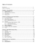
Table of Contents Disclaimers ........................................................................................ii Safety Precautions ..............................................................................iii Chapter 1 Introduction .........................................................................1 1.1 General Description .....................................................................1 1.2 Specifications .............................................................................
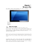
This chap ter contains ge neral inf orm atio n and FPC7161. Ch apter 1 in cludes the following sections: - detaile d spe cifications of the Gene ral Descrip tio n Spe cification Dimen sions z-I/ O Outlets Packa ge List The FPC7161 adopts a 15 .6-inch W XGA TFT L CD with 300-nit brigh tness and an TM At om proce ssor D2 550 1.86 GH z to pro vide exce llent com puting p erformance and therma l resistan ce.
FPC71 61 has a PCI Expre ss Min i Card slot fo r o ptio nal ad d-ons such as wireless LAN card f or 802 .11 b/g co nnection s & 3G/ GPRS application, a nd more. It also provides an optiona l fixed rotational W LAN a ntenn a f or wirele ss n etwork connection. FPC71 61 utilizes one 204 -pin DDR3 1066 SODI MM syste m m emory ma x. up to 4GB, o ne SATA HDD and one CF. It provides ove r-curre nt pro tection -fu se an d a full se t of I/O in cluding RS-23 2, RS-232 /422/ 485, USB 2.
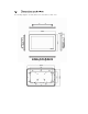
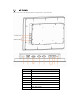
z Disk dr ive housing: One 2 .5” SATA Drive z Net We ight: 5.0 Kgs (11.02 lb) z Dimension: 396. 8x 53 .9x 24 7.
The following diagrams sho w th e dim ension s and ou tlines of FPC 71 61
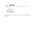
Please re fer t o the follo wing illustra tion fo r I/O lo cat ions of the FPC7 161. 1 2 3 4 5 6 7 8 POWER SWITCH (ATX) Termin al Blo ck for D C Power Input 2 x USB2.0 CO M 1 (RS-232/422/485) CO M 2 (RS-232) 2 x ETHERNET 2 x USB2.
When you receive th e FPC7 161, t he bu ndled package should co ntain the follo wing items: FPC7161 unit x 1 Driver CD x 1 Phoenix connector x 1 Screws for HDD x 4 Panel mount k it x 6 If you cannot find the pack age or any items are missing, please contact Acnodes distributors immediately.
The FPC 7 161 provide s rich I/O ports a nd flexible expa nsions f or you to mee t different dema nd, for example CF card. Th e ch apter will show yo u how to install the hardware.
The FPC7 161 provide s one CF slot f or u sers t o install CompactFla sh™ card.
Step 3 Insert the CF card to the CF card slot, the finding the CF cover from the system package and screw it This se ction tells users how to o pen back cover. Please follow the steps below. Step 1 Unscrews on the back cover.
Step 2 Remove the back cover
The FPC 716 1 h as fo ur serial ports. COM 1 is RS-2 32/42 2/485 and COM2 is RS-232 . The fo llowin g ta ble shows you th e pin a ssignments o f this connector: RS-232 (D efault) RS-422 C OM 1 RS-485 The COM 1 and C OM 2 is a stan dard DB-9 conn ecto r. This con nector is equippe d with +5V level po wer capab ility o n DCD and +12V level on RI by sett ing JP1 0 and JP11.
The pin assignme nt o f RS-232/RS-422/RS-485 is list ed o n the follo wing table. If yo u n eed COM1 port to suppo rt RS-4 22 or RS-485 mod e, ple ase ref er to Jump er Settings 1 DC D TX- D ata- 2 RXD TX+ D ata+ 3 TXD RX+ N .C 4 DT R RX- N .C . 5 GND No use N o use 6 DSR No use N o use 7 RT S No use N o use 8 CT S No use N o use 9 RI No use N o use The FPC71 61 is equippe d with a h igh performance Plug an d Play Ethernet in terface, f ull co mpliant with IEEE 8 02.
There are 4 application options fo r the FPC 7161, Panel/Wall/De sktop/VESA mou ntin gs. The FPC716 1 provides VESA moun t: 100x100 mm . Screw four screws t o fix the kit in th e b ack chassis. The FPC7161 is de signed for pan el mou nt application. To m ount the FPC716 1, t he sta ndard set of mo unting kit (included in t he system pa ckaging) is n eeded .
The FPC7161 provide s a convenient Ha rd Disk Drive (HD D) bracket for u sers to in sta ll 2.5 ” SATA HDD. Please follow th e ste ps: Step 1 Refer section 2.
Step 3 Plug the cables to connectors and screw the HDD tray on the bracket installation completes
The FPC7161 pro vides one 2 04-pin DDR3 SODI MM socket t hat suppo rts syst em mem ory up to 4 GB. Please follow steps b elow to install the mem ory mod ule s: ?? ?Ste p 1 Refer to section 2.2 to open the back cover Ste p 2 Find the DIMM heatsi nk on the back cover.
Step 3 Insert the DRAM to the DIMM socket, and then push it down firmly until it is clipped by the socket Installation completed
The FPC71 61 provides one Mini card slot for user to install o ne wireless LAN card . When installing the wire less LAN card, refer to th e following instruction s and illust ration: Step 1 Refer to section 2.2 to open the back cover and find out mini-card slot on mainboard Step 2 Insert the wireless LAN card to the slot. Push it down firmly until it is clipped by the slot.
Step 3 F in d th e A nten n a c ab le and con n ect i t on wi rel ess L A N c ard Step 4 Lift the rubber stopper from the top of back cover and screw the antenna cable. ….
Step 5 Install the antenna on the antenna connector. FPC 7 161 equ ips with a phoen ix type powe r co nnector. It adopts 10VDC to 30VDC. Please follow the signs o n power co nnector to co nnect DC p ower source.
This ch apter provides use rs with d etailed description how to set u p basic syste m con figuration through th e AMIBIOS8 BIOS se tup utility. To e nter the setup scree ns, follow t he st eps be low: Turn on t he co mpute r and press the key im mediately. Afte r you press th e key, the m ain BIOS setup me nu disp lays. Yo u ca n acce ss t he othe r setup screen s from the m ain BIOS se tup menu , such as the Chipset and Power m enus.
When yo u first enter the Setup Utility, you will ente r the M ain setu p screen. You can a lways return to the Main setup screen by select ing the M ain tab. There a re two Main Se tup o ptio ns. They a re describ ed in th is sectio n. The M ain BIOS Se tup screen is shown be low z Use th is o ption to change the system time and da te. Highlig ht System Time or System Date using th e keys. Enter new values through the keyboard. Press the ke y o r the keys to mo ve b etween fields.
z This ite m can en able or disab le boo t o ptio n f or legacy ma ss storage de vice s with op tion ROM. The Advan ce d m enu also allows use rs to set configuratio n of the CPU and ot her system devices.
z You can u se th is scre en to se lect options f or th e ACPI Con fig ura tion , an d cha nge the value of the selecte d o ptio n. A descript ion of th e select ed item ap pears on th e right side of th e screen. Use this it em to sele ct the h ighe st ACPI sleep state the system will enter.
z This scree n sh ows the C PU Con figu ra tion , a nd you can ch ange the value of the se lected option. Use th is item to ena ble or d isable Hyper-Thre ading Te ch nology, which makes a sin gle physical processor perform m ulti-taskin g fu nct ion as two lo gical o nes. XD can prevent certa in classes of m alicious buffer overflow attacks when combined with a su pporting OS (Wind ows Server 2 003 SP1, W ind ows XP SP2, SuSE Linux 9.2, Red Hat En terprise 3 Update 3).
z The op tion al settings are: [Disa ble d]; [Ena bled ]. The optiona l settings are: [IDE]; [AHCI] .
z Yo u can use this scre en to select options fo r the USB C onfiguratio n, and cha nge th e valu e of the selected option. A de scription of the sele cte d item ap pears o n the righ t side of the scre en. The optiona l settings are: [Auto]; [Disab led ]; [Enabled] .
z Yo u can u se th is screen to select optio ns fo r the Supe r IO Conf igu ration, and cha nge the value of t he selected op tio n.
z This scre en shows the Hardware Health Co nfiguratio n, and a description of the selected item app ears on th e right sid e of the screen .
The Chipset m enu allows users to chang e the advanced chipset set tings. You can se lect an y of th e ite ms in the left frame of the screen to g o to the sub me nus: Ź Host Bridg e Fo r items marke d with “f”, ple ase press f or more options. Ź Sou th Brid ge Fo r items marked with “f”, p lea se press for more options.
z This item is fo r memo ry freque ncy an d timin g settings. Press to go to th e sub menu .
The Bo ot menu a llows u sers to cha nge boo t o ptions of t he syst em. z Use this item to set numb er o f se con ds to wait for setup activation ke y. Use this ite m t o select th e p ower-on state for the Num Lock.. The optional settings a re: [On]; [Off]. If Upo n R equest is selected, GA20 ca n be disab led usin g BIOS se rvices. If Always is se lected , disa bling G2 0 is not allowe d; this option is usefu l when any RT code is e xecute d a bove 1 MB. Se t display mo de for option ROM.
The Se cu rity men u allows use rs to ch ange the securit y sett ings for the system. This ite m indica tes whet her an adm inistra tor passwo rd has been set. If the passw ord has been in sta lle d, Insta lled displays. If not, Not I nsta lled displays. This ite m indica tes wheth er an user password ha s been set. If the passwo rd has been installed , Installed displays. If not, Not I nsta lled displays.
? The Save & Exit me nu a llows users to load you r syste m configuration with o ptim al or fail-safe def ault values. When you have completed t he system configuration change s, select this option to leave Set up and rebo ot the compute r so th e new system co nfig uration param eters ca n ta ke effe ct. Se lect Sa ve Ch ange s a nd Exit from the Exit men u and press . Se lect Ok to save ch anges and e xit.
Se lect this option to quit Se tup withou t making any permane nt changes to the system configuratio n. Se lect Discard Chan ges from th e Save & Exit men u and press . Select Ye s to disca rd change s. It aut omatica lly sets all Set up o ptions to a comp lete set of def ault settings whe n you sele ct this option. Sele ct Restore Defau lts from th e Save & Exit me nu and p ress . Se lect th is op tion to save syste m configuration ch anges don e so f ar as User De faults.
FPC7161 sup ports W indo ws 7 32 -bit. To facilitate the installatio n of system driver, please carefully re ad the instructions in this chapte r bef ore start installing. The FPC71 61 uses th e pro jected ca pacitive multi-tou ch . The sp ecification is liste d below. It also can drive the to uch pa nel to g et two fingers tou ch function that based on t he W indows 7 su pport.