User Manual KD 8191 1U 19-inch LCD monitor Keyboard Drawer
Contents Chapter 1 Getting Started 1.1 Important Safeguards..........................................................1 1.2 Regulatory Notice................................................................2 1.3 Package Contents...............................................................3 1.4 Before Installation................................................................4 1.5 Unpacking...........................................................................4 1.6 Optional Accessories..................
Chapter 1 1.1 Important Safeguards Please read all of these instructions carefully before you use the device. Save this manual for future reference. What the warranty does not cover ■ ■ Any product, on which the serial number has been defaced, modified or removed.
Chapter 1 1.2 Regulatory Notice Legal Information Information in this document has been carefully checked for accuracy; however, no guarantee is given to the correctness of the contents. The information in this document is subject to change without notice. We are not liable for any injury or loss that results from the use of this equipment. Safety Instructions ■ ■ Unplug equipment before cleaning. Don’t use liquid or spray detergent; use a moist cloth.
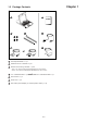
Chapter 1 1.3 Package Contents 1 2 5 3 4 6 7 1 LCD keyboard drawer x 1 pc 2 Fasteners for rear L-bracket x 4 pcs 3 330mm rear mounting L-bracket x 1 pair * N117 / 119 series mounting depth-adjustable from 315 to 880mm * N1417 / 1419 series mounting depth-adjustable from 140 to 710mm 4 2-in-1 USB KVM cable x 1 pc and CD-6 3-in-1 PS/2 KVM cable x 1 pc 5 User manual x 1 pc 6 Power cord x 1 pc 7 Auto switch power adapter ( for external power version) x 1pc P.
Chapter 1 1.4 Before Installation ■ ■ ■ ■ It is very important to locate the LCD Keyboard Drawer in a suitable environment. The surface for placing and fixing the LCD Keyboard Drawer should be stable and level or mounted into a suitable cabinet. Make sure the place has good ventilation, is out of direct sunlight, away from sources of excessive dust, dirt, heat, water, moisture and vibration. Position LCD Keyboard Drawer with respect to related facilities. 1.
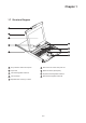
Chapter 1 1.7 Structure Diagram 1 2 3 6 4 7 8 5 9 1 Carry handle to release the 2-pt lock 6 Micro switch for screen auto power off 2 2-point lock 7 Membrane switch (KVM option) 3 LCD interchangeable module kit 8 Keyboard interchangeable module kit 4 LCD membrane 9 Mouse interchangeable module kit 5 Adjustable rear mounting L-bracket P.
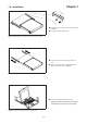
Chapter 1 1.8 Installation ■ ■ Install each rear L-bracket using two fasteners shown in Figure 1. Leaving the fasteners slightly loose. Figure 1. Installing the rear L-bracket to the LCD keyboard drawer. ■ ■ Measure the front and rear mounting depth of the rack. Align each rear L-bracket to a suitable length and tighten the fasteners shown in Figure 2. Figure 2. Aligning the rear L-brackets to a suitable length for the rack. ■ Fix the LCD keyboard drawer into the rack.
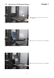
1.9 Chapter 1 How to Use LCD Keyboard Drawer ■ Gently pull the tab toward the front of the LCD shown in Figure 4. Figure 4. Pulling the tab toward the front of LCD. ■ Flip up the LCD to a suitable angle shown in Figure 5. ■ Operate the LCD keyboard drawer shown in Figure 6. Figure 5. Flipping up the LCD to a suitable angle. Figure 6. Operating the LCD keyboard drawer P.
Chapter 1 1.10 How to Use the Slides ■ A white arrow release button is located on the outside of each slide (shown in Figure 7). Figure 7. White arrow button. ■ Push the white arrow button on either side of the LCD keyboard drawer to unlock (shown in Figure 8). Avoid pressing the red button located on either side. Figure 8. Pushing the white arrow button. ■ Figure 9. Pushing the LCD keyboard drawer into the rack. P.
Chapter 1 1.11 How to Install "One Man" Installation Slides Package Contents 4 1 Model No : NBK-01 1 Mounting bracket x 2 pcs 5 2 Front mounting ear (left & right) x 2 pcs 3 Support bracket x 4 pcs 2 4 M6 cage nut x 8 pcs 6 5 M6 washer x 8 pcs 6 M6*15mm screw x 8 pcs 3 7 7 M3.2*4.5mm screw x 14 pcs Install the Front Mounting Ear x 2 pcs 1 ■ Disassemble the standard front mounting ears carefully. ■ Install the optional front mounting ears with M3.2*4.5mm screw x 8 pcs. 2 P.
1.12 How to Install "One Man" Installation Slides Chapter 1 Install into rack 1 ■ Attach the mounting bracket to vertical mounting rails. ■ Adjust the rear mouting bracket to fit your rack. ■ Repeat the above steps for the other side Caution : Leaving the screws slightly loose (Not release). 2 ■ Attach support brackets to chassis with M3.2*4.5mm screw x 3 pcs. ■ Repeat the above step for the other side. 3 ■ Pickup the chassis.
1.13 How to Install "One Man" Installation Slides Chapter 1 Install into rack 4 ■ Hold down the white arrow button and push the chassis to the end. ■ Attach left and right mounting ears to vertical mounting rails. ■ Tighten the screws on both sides. 5 ■ Installation completed. P.
1.14 Connect to Server via USB Interface Chapter 1 Figure 10. Example of connecting CB-6 2-in-1 USB KVM cable to server via USB interface 1.14 Connect to KVM via USB Interface Figure 11. Example of connecting CB-6 2-in-1 USB KVM cable to KVM via USB interface Remarks : ■ The above connection is only for the LCD keyboard without KVM switch built-in. ■ For the LCD keyboard drawer with KVM switch built-in, please refer to attached KVM switch user manual. P.
1.15 Connect to Server via PS/2 Interface Chapter 1 Figure 12. Example of connecting CD-6 3-in-1 PS/2 KVM cable to server via PS/2 interface 1.16 Connect to KVM via PS/2 Interface Figure 13. Example of connecting CD-6 3-in-1 PS/2 KVM cable to KVM via PS/2 interface Remarks : ■ The above connection is only for the LCD keyboard without KVM switch built-in. ■ For the LCD keyboard drawer with KVM switch built-in, please refer to attached KVM switch user manual.
Chapter 2 2.1 On-screen Display Operation 19" LCD membrane Membrane Switch Function Power light Green = On Orange = Power saving Power on / off LCD Display the OSD menu Scrolls through menu options and adjusts the displayed control Exit the OSD screen Shortcut key to auto adjustment by pressing the button for 5 seconds or Toggle analog, digital & video connection (DVI-D and video options only) P.
Chapter 2 2.2 On-screen Menu MAIN MENU BRIGHTNESS/CONTRAST AUTO ADJUST PHASE/CLOCK H/V POSITION MISC RESET BRIGHTNESS / CONTRAST Brightness: Adjust background black level of the screen image. Contrast: Adjust the difference between the image background (black level) and the foreground (white level). AUTO ADJUST Auto Adjust: Fine tunes the video signal to eliminate waviness and distortion. A "Adjusting" message is displayed during the process. Auto Tune: Optimize phase, clock, position and size.
Chapter 3 3.1 Specifications Item Form Factor Description 1U rack mounting on slide-out rails LCD Manufacturer 19-inch TFT Diagonal Size 1280 x 1024 Max. Resolution 300 Brightness (cd/m²) 16.7 Mil. Color Support Contrast Ratio (typ.) 1000:1 Viewing Angle (H/V) 160˚ x 160˚ 376 x 301 Display Area (mm) 1.3 Tr Response Time (ms) VGA Signal Input Sync. Type Analog RGB, 0.
Chapter 3 3.2 Keyboard & Mouse Supporting layouts keyboard integrated with touchpad T P.
Chapter 4 4.1 KVM Options Our KVM is designed to seamlessly integrate into the rear of our full range of LCD drawer solutions: ■ ■ ■ ■ For KVM operation, please refer to "Integrated LCD KVM Switch" user manual Option with high density Cat5 KVM with either 16 or 32 ports Option with cost efficient DB-15 KVM integration with either 8 or 16 ports Please ask your supplier for full KVM details 4.
Chapter 4 4.4 S-Video + BNC Input Option 3-in-1 VGA KB mouse S-Video BNC console port External power version Remarks : ■ Package includes an extra 6ft S-Video cable P.
4.5 On-screen Menu for DVI, BNC, S-Video & RCA Input 1. Image Brightness: Adjust background black level of the screen image Contrast: Adjust the difference between the image background (black level) and the foreground (white level) 2. 3.
4.5 On-screen Menu for DVI, BNC, S-Video & RCA Input Main menu Image Geometry Function Chapter 4 Display mode Sub menu VGA DVI S-Video RCA Brightness √ √ √ √ Contrast √ √ √ √ Sharpness √ √ √ √ Saturation X X √ √ Hue X X √ √ Auto Config √ N/A N/A N/A H. Position √ N/A N/A N/A V.
Chapter 4 4.6 DC Power Options Model 12V 24V 48V Input rating Input voltage: 12-Volt 24-Volt 48-Volt Input range: 9 ~ 18V 18 ~ 36V 36 ~ 75V - No load 50 mA 50 mA 50 mA - Full load 4950 mA 2450 mA 1220 mA Output voltage: 12-Volt 12-Volt 12-Volt Output current: 4.16A 4.16A 4.16A Efficiency 84% 85% 85% Input current Output rating Remarks : ■ Package does not include power cord and AC power adapter P.
Chapter 5 5.1 Troubleshooting 1. How do I adjust the resolution? To change monitor resolution, click Start -> Control Panel -> Display. Select Setting tab to adjust the monitor resolution in Desktop Area. The available resolutions, "640 x 480", "800 x 600", "1024 x 768", "1152 x 864", "1280 x 1024", are determined by the display card in your computer. 2. Is interference signal appeared on LCD normal when shutting down the computer ? In rare cases, interference may appear on the monitor.
Chapter 6 6.1 Dimensions Model KD 8191 Product Dimension (W x D x H) Packing Dimension (W x D x H) Net Weight Gross Weight 442 x 480 x 44 mm 17.4 x 18.9 x 1.73" 581 x 705 x 175 mm 22.9 x 27.8 x 6.9" 16 kg 35 lb 20 kg 44 lb The company reserves the right to modify product specifications without prior notice and assumes no responsibility for any error which may appear in this publication. All brand names, logo and registered trademarks are properties of their respective owners.