User Manual KDI815x/KDI817x/KDI819x 15” / 17”/ 19” LCD x = 8 /16 ports IP KVM with Remote Console
User Manual 1. Table Of Content 1. Table of Content P.1 2. Introduction P.2 3. Features P.2 4. Package Contents P.3 5. Optional Accessories P.4 6. Peripheral Products P.4 7. Important Safeguards P.5 8. Structure Diagram P.6 9. Dimension Diagram KDI 8158/81516 KDI 8178/81716 KDI 8198/81916 P.7 P.8 P.9 10. LCD Session P.11 P.12-13 Main Menu Sub Menu Resolution Settings For Windows For SUN Servers P.14 P.15 11.
User Manual 2. Introduction KDI Series is a combination of keyboard, mouse and monitor into a drawer, with features such as flip-up design, adjustable brackets, built in LCD OSD to provide effective assistant for an administrator to control PC system. KDI Series provides cost effective for your limited IT budget over using CRT and rack mounting. Also, it will be space saving for your compact environment rack and effective assistant for an administrator to control PC system. 3.
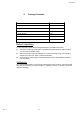
User Manual 4. Package Contents LCD Monitor Drawer with IP KVM Switch 1 Piece User Manual 1 Piece DC Power Adapter 1 Piece Power Cord 1 Piece Mounting Bracket 1 Pair Fasteners 4 Pieces CD-6 3-in-1 KVM cable 8 Pieces Before Unpacking It is very important to locate the LCD Keyboard Drawer in a suitable environment. ● The surface for placing and fixing the LCD Keyboard Drawer should be stable and level or mounted into a suitable cabinet.
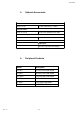
User Manual 5. Optional Accessories KVM Cable CD-6 / 10 / 15 6ft / 10ft / 15ft PS/2 3-in-1 cable Cascade Cable CA-2 / 6 / 10 / 15 2ft / 6ft / 10ft / 15ft PS/2 3-to-3 cable Conversion Adapter SUN-31 SUN / iMAC USB to PS/2 adapter Others Video Input 12V / 24V / 48V DC Power Supply 6. Rev. : 1.
User Manual 7. Important Safeguards Please read all of these instructions carefully before you use the device. Save this manual for future reference. ● ● ● ● ● ● ● Unplug the LCD Keyboard Drawer from the power outlet before cleaning. Do not spray liquid cleaners or aerosol directly on the device. Wet a cloth with a neutral detergent (e.g. clean water) and squeeze it tight, then clean the screen slightly with it. Do not expose the LCD Keyboard Drawer directly to rain, water, moisture or sunlight.
User Manual 8. Rev. : 1.0 Structure Diagram 1. PS/2 keyboard 2. Aluminium front panel 3. Class A active matrix TFT LCD panel 4. Rear metal case 5. LCD inverter 6. LCD membrane 7. Ball bearing telescopic slides with stopper 8. Adjustable mounting bracket 9. Optional KVM switch P.
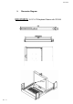
User Manual 9. Dimension Diagram KDI 8158/16 1U 15” LCD Keyboard Drawer with IP KVM 15” LCD Rev. : 1.0 P.
User Manual 9. Dimension Diagram KDI 8178/16 1U 17” LCD Keyboard Drawer with IP KVM 17” LCD Rev. : 1.0 P.
User Manual 9. Dimension Diagram KDI 8198/16 1U 19” LCD Keyboard Drawer with IP KVM 19” LCD Rev. : 1.0 P.
User Manual LCD Session Rev. : 1.0 P.
User Manual 10.
User Manual 10. LCD Session Bright / Contrast 1. Brightness ● To perform brightness adjustment of the input RGB signal ● Use the Left & Right button to adjust and button to “Brightness” 2. Contrast ● To adjust the contrast level of the input signal ● Use the Left & Right button to adjust and button to “Contrast” Phase / Clock 1. Phase ● To adjust input video sampling clock’s phase ● Use the Left & Right button to adjust and button to “Phase” 2.
User Manual 10. LCD Session MISC 1. Information ● ● ● The first header row shows the current resolution setup The second header row shows the horizontal frequency of the current input signal The third header row shows the vertical frequency of the current input signal 2. OSD Timer ● To modify the duration of the OSD time-out 3. Color a) 5500K ● Select Colour Temp at 5500K b) 6500K ● Select Colour Temp at 6500K c) 9500K ● Select Colour Temp at 9500K d) User ● Change Colour Temp by manual 4.
User Manual 10. LCD Session Resolution Settings For Microsoft Windows Step 1 – Press right click on the desktop Step 2 – Choose “Properties” Step 3 – Change the “Screen Resolution” Step 4 – Change the “Screen refresh rate” Rev. : 1.0 P.
User Manual 10. LCD Session Resolution Settings For SUN Servers ● ● ● ● ● ● ● ● Resolution configuration procedures should be run by qualified SUN server administrator Sun Servers are using resolution at 1152 x 900 x 76Hz. Supported resolution mode for 15” LCD: 1024 x 768 x 70/75Hz Supported resolution mode for 17” LCD: 1280 x 1024 x 75Hz You need to change the Sun Server resolution before you connect to LCD Display. Please do the following procedures to change the resolution settings : 1.
User Manual KVM Session Rev. : 1.0 P.
User Manual 11. KVM Session Front View Channel Select Button Selected Channel LED 16 PORT BANK No. Online Channel LED BANK Button 1 2 3 4 5 6 7 8 8 9 10 11 12 13 15 16 PC Ports B S Shift Button Channel Select Button Selected Channel LED BANK No. Online Channel LED 8 PORT 1 2 3 4 5 6 PC Ports 7 8 Reset B BANK Button LED Indication Selected Channel LED - Displayed channel on monitor & red in LED. Channel select button - Press to select channel from 1 – 8.
User Manual 11. KVM Session Rear View l k k o n m j Figure 11-1. Identifying IP KVM rear panel components Rear Panel Components Location Rev. : 1.0 Component j 8 or 16 PC Ports k Serial Port l RJ-45 LAN Port m Cascade Port n Virtual Media USB Port o DC Power Input P.
User Manual 11. KVM Session Installation Steps Step 1. Connect the included power adapter to IP KVM and switch on. A beep sounds and “BANK No.” LED indicated the current bank status. DC Power Input Figure 11-2. Identifying IP KVM rear panel components Step 2. Connect the Local Console of KVM to Input device and Display Unit. Local Console Device (Monitor, Keyboard & Mouse) Figure 11-3. IP KVM Rear View Step 3.
User Manual 11. KVM Session Step 4. Connect the IP KVM to your Servers using the provided KVM cables* (Fig. 1) VGA HDDB-15-pin connector on KVM cable (Blue) PS/2 mouse connector on KVM cable (Green) PS/2 keyboard connector on KVM cable (Purple) Figure 11-4. PS/2 KVM Cable Server connectors PS/2 keyboard port of your server PS/2 mouse port of your server VGA HDDB 15-pin display output port of your server Step 5. Connect IP KVM to the network for remote control purpose.
User Manual 11. KVM Session Cascading Using CA-6 PS/2 KVM cable to connect from Bank 1’s “Cascade port” to Bank 2’s “Console port”. After connected please press “Bank” & “Channel” button on the front of the PS/2 KVM switch to reset the PS/2 KVM switch. Bank 1 Figure 11-6. IP KVM Rear View Bank 2 Bank 8 (Max.) CA-6 PS/2 KVM cable Figure 11-7. PS/2 KVM Rear View CA-6 PS/2 KVM cable Figure 11-8. PS/2 KVM Rear View Cascade level Max. : 8 level Rev. : 1.0 ● Max.
User Manual 11. KVM Session Remote Access the IP KVM Device Factory Default Information: IP Address : 192.168.1.22 Subnet mask: 255.255.255.0 Gateway : none Login name : super Passwords : pass Step 1. Open your java enabled browser, e.g.: Internet Explorer 6, Netscape, Mozilla, FirFox.. Step 2. Enter the IP address of the IP KVM in the address box. http://192.168.1.22 Enter Username “super” (Factory default) Enter Password “pass” (Factory default) Figure 11-9.
User Manual 11. KVM Session IP KVM web base interface j k l m no q p Figure 11-10. Main page of IP KVM IP KVM Configurations Location Function j KVM Console & Telnet Console setup k Virtual Media setup l Change Password and User management m User Console, Keyboard, mouse and Video settings n Network, Serial port, security, date, log view settings o Device Status, Firmware upgrade, Event log & Unit reset p Log off user and exit from IP KVM.
User Manual 12. Start Up 1. The channels that have PC connected and it is switch on will have a green LED on that channel. 2. The red LED will indicate the selected channel. 3. 7 segments LED will display the bank number. 4. Press channel button to select the channel. 5. Enter the password, default is “00000000” eight zeros. 6. Otherwise the keyboard & mouse will be locked. 7. If you forget your password, send back to Manufacturer. HotKey Command Rev. : 1.0 ● Simple key sequence.
User Manual 12. Start Up Hot-key Command Operation 1. Calling OSD Menu Scroll 2. Space Bar Scroll + £ + Switch to Next Power On Port (powered on PC only) Scroll 4. + Switch to Previous Port (powered on PC only) Scroll 3. Scroll + Scroll + ¤ + Switch to Previous Bank Scroll Scroll + First digit of Port Number: 0 for Port 0-9 1 for Port 10-16 Pg Up + Second digit of port Number 5. Switch to Specific Port Scroll Scroll + Bank 1~8 + No. 0 or 1 + No.
User Manual 12. Start Up HotKey Command Operation 6. Switch to Next Bank Scroll 7. Scroll + + PgDn Enable / Disable beeper sound Scroll Scroll + B + Note: The default Beeper function is ON and beeper control is only for 8. Auto Scan for Powered on PC Scroll Scroll + 9. S + Reset to factory Default Setting Scroll Scroll + ROM REFLASH R + Note: Not available for password reset. 10.
User Manual 12. Start Up OSD Structure Diagram Bank Session BANK : 1 01 SYSTEM 01 02 SYSTEM 02 03 SYSTEM 03 04 SYSTEM 04 PC Session 05 SYSTEM 05 06 SYSTEM 06 07 SYSTEM 07 08 SYSTEM 08 OSD : 1 0 SEC. CHANGE PASSWORD SCAN: 1 0 SEC.
User Manual 12. Start Up KVM Settings Session 1. OSD ● ● 2. ● Choose “Change Password” in KVM Setting Session. Key-in the existing password. ● Enter the New Password. ● Re-Enter the New Password. ● Changing Password complete. The steps are shown as next picture: Console On/OFF ● ON – any user can use the console ● ● Rev. : 1.0 It can be modified to 99 seconds for maximum. ● ● 5. Scan interval from one PC port to next PC port when applying auto scan, its default is 10 seconds.
User Manual 13. FAQ 1. Don’t press any keys on the keyboard while the selected computer is booting up. Otherwise, it might cause the keyboard error or keyboard is not detected at PC side. 2. The computer boot up fine, but keyboard doesn’t work. ● Make sure the keyboard works when directly plugged into the computer. ● Try a different keyboard, but use only 101, 102 or 104-key keyboard. 3. The Mouse is not detected during PC boot up. ● Make sure the mouse works when directly plugged into the computer.
User Manual 14.
User Manual 14. Technical Specification of LCD LCD Description Item LCD Screen Manufacturer LCD Origin Panel 15” TFT South Korea 15” TFT 17” TFT 19” TFT Resolution 1,024 x 768 1,280 x 1,024 1,280 x 1,024 Brightness 2 450 cd/m 300 cd/m 300 cd/m2 Color 16.2 Million 16.2 Million 16.7 Million 400:1 700:1 700:1 140° x 115° 150° x 135° 150° x 135° 304 x 228 mm 337 x 270 mm 376 x 301 mm 0.297 mm 0.264 mm 0.294 mm Response Time (Tr) 5ms 2ms 1.